

Hardware components | ||||||
| × | 1 | ||||
| × | 1 | ||||
| × | 4 | ||||
Hand tools and fabrication machines | ||||||
 |
| |||||
A couple of years ago I got this fogger on eBay pretty cheap. It needed some help. The pump was stuck, so I disassembled it and got it cleaned out and working again. I wanted to use it for Halloween this year, but I don't want to have to press the button every few minutes. A long time ago I made a long interval timer that would be perfect for this. I know they make a timer for $20 but that's almost what I paid for the fogger.
Step 1: Remote PendantFirst thing was to see what's inside the remote pendant. Wow, a switch and a light. That's easy. It uses a standard computer IEC connector so I don't even have to hack up the original cable. I had a couple of IEC jumpers laying around.
There's so much room in that pendant that I was tempted to put a relay in there with a headphone jack connected to the coil. Then I could hook that into the doorbell and be done.
If you're looking for a quick way out, that would be it.
Step 2: What's inside the big boxI never take the easy way out when it means there's a gadget that won't be built. From the way it's wired, the white and black wire are connected directly to the power line. That's great since it means I can use them to power a small transformer to run the micro-controller; that opens up a whole bunch of possibilities.
Step 3: The ControllerSo, now I have a source of 110V power and if I add a CDS cell and a neon light I can even get a signal to the micro to tell me when the machine is ready. In this machine the light is ON until the machine is ready. When it goes out then you can hit the button. That pumps a little of the fog juice into the hot chamber vaporizing it.
This was the only non-standard part of the build. I mounted them so the CDS cell was facing the center of the tube and covered it with heat shrink tubing. I pinched the top of the tube shut with a pair of needle nose pliers while it was still hot.
There is a warning in the manual to not hit the button before the light goes out. Oddly, the pump is wired across the thermostat so it won't get any power until the machine is hot. That kind of eliminates the need for the ready light since the controller can pulse the thing all day long and it wont hurt anything.
I added it anyway so the LCD can show a status of "Heating" or "Ready" along with the timer settings.
The UI is simple 4 pushbutton switches Dur+ Dur- Int+ Int- to set the duration and interval and a toggle switch to turn it off. The duration is in millisecond increments and allows for 100 to 1500 milliseconds (.1 to 1.5 Seconds). The interval is in second increments and allows for 30 to 600 seconds between pulses. These limits can easily be changed.
Maybe another feature in V2 will be a float sensor to stop the timer if the tank goes empty. That brings with it a third status of "Fill Tank". I added the code but it's too close to Halloween to get a float switch installed. For now I'll leave a jumper on that connector.
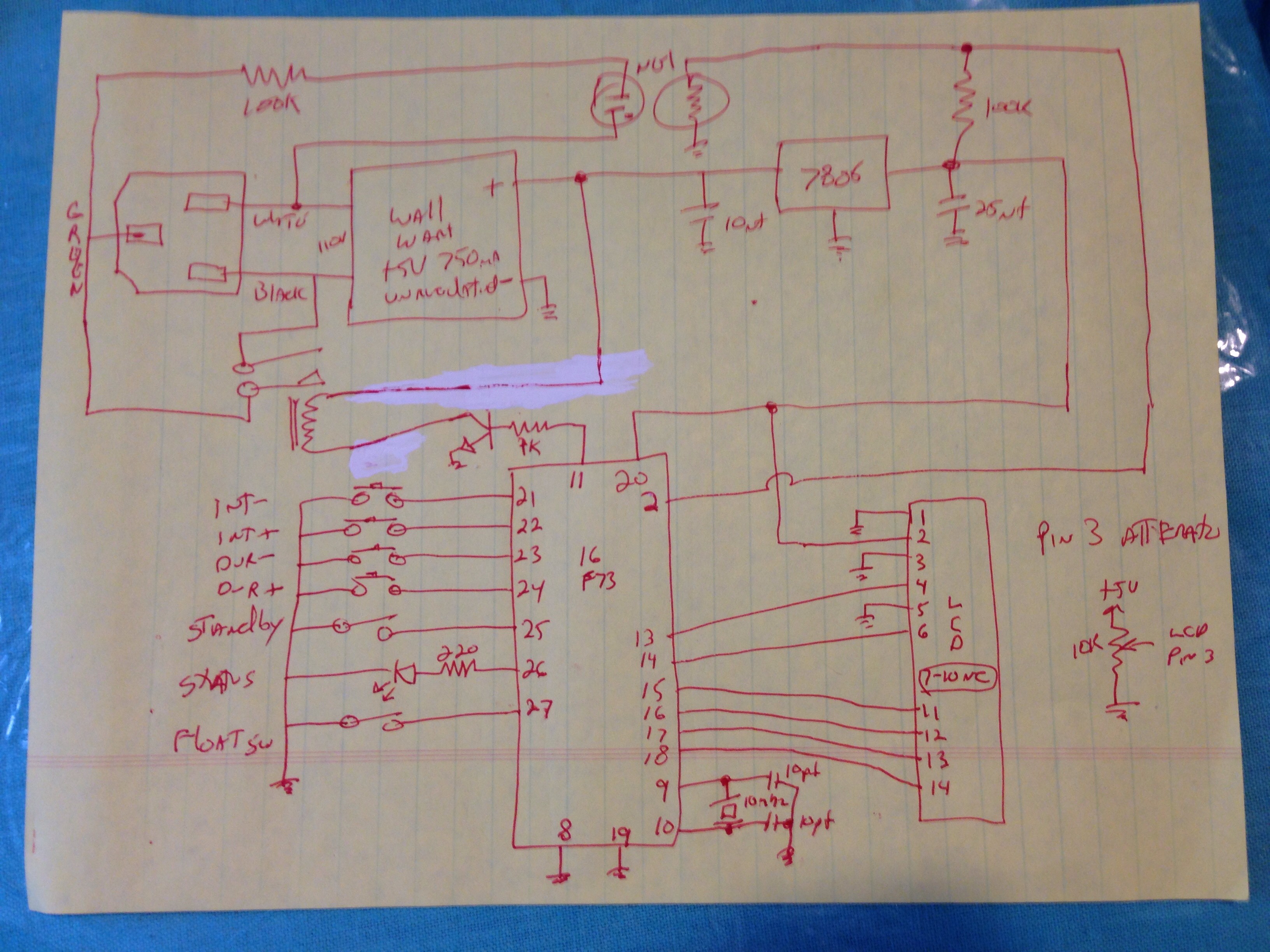
Step 4: Schematics and CodeI wrote this in PicBasicPro. There is a free student version of picbasic available online you can use if you want to try it. I tried redrawing the schematic but its still a little sketchy. You can omit the pull up resistors on the front panel switches since the pic has internal weak pull ups. I like to add 1K resistors anyway.
I used a 10Mhz ceramic resonator in place of the crystal and 2 caps on pins 9 and 10. Either way is fine. When I tried to test it with a stop watch I got a measured time of 1 minute and 59.96 seconds when set to 120 seconds. Close enough for me.
Step 5: +5V PowerI used a small wall wart and attached it to the side by using longer screws through the existing screw holes. This keeps it neat and simple. It's really handy to have some small screwdrivers to get in there and tighten those screws.
It looks pretty neat and the original cable exit is perfect for the power cord.
Step 6: Putting it all TogetherThe board was left floating in the case. I should mount it but I'll have to wait till after Halloween to do that.
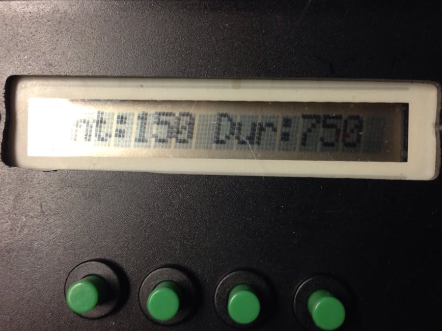
I used a 16F73 micro-controller that doesn't have EEPROM so there is no permanent setting storage. The next version will get and upgrade to a 16F876 which has non-volatile memory. Then when you change the interval and duration, it will be stored for use at the next power up. Right now, it always defaults at power up to 750 mS pulses every 150 Seconds.
The two chips are pin compatible so its just a firmware update needed.
I did add a status LED that blinks when operating so I have a heartbeat. The next version changes to a bi-color LED, so it's either a green heartbeat, a yellow standby indicator, or a red error indicator.
It's not pretty and nothing is labelled yet, but its fully operational in time for Halloween!
Step 7: Danger Will Robinson.Just a little warning: no matter how tempting it is, don't use a computer cable to plug this into a power outlet. The first time the relay fires it will connect the ground to the hot line!
My first thought was to use a hollowed out power brick to house the controller since I had one on the shelf. That only increases the risk that some unsuspecting person would plug it in the wall.
I would suggest adding 750mA fuses to each lead from the cable.
Even worse, if you plugged the unmodified factory pendant into the wall, it would burn your finger when you hit the button. It's easy to see that the button is connected between the black and green wires. It's such a cheap switch, it would pop violently when you pushed it. I'd add fuses to that pendant too.
It's just a poor design from the factory and one that many of these machines share. Even in its unmodified form right out of the box its dangerous to a beginner who thinks "Hey I know what goes in there".


Comments