

Hardware components | ||||||
| × | 1 | ||||
| × | 1 | ||||
| × | 1 | ||||
| × | 1 | ||||
 |
| × | 1 | |||
 |
| × | 1 | |||
| × | 1 | ||||
| × | 1 | ||||
| × | 1 | ||||
| × | 1 | ||||
| × | 1 | ||||
| × | 15 | ||||
| × | 4 | ||||
 |
| × | 6 | |||
| × | 1 | ||||
Software apps and online services | ||||||
 |
| |||||
| ||||||
 |
| |||||
Hand tools and fabrication machines | ||||||
 |
| |||||
 |
| |||||
 |
| |||||
 |
| |||||
 |
| |||||
>>> See Demo Here <<<
Every morning and every night either my wife, or I, used to turn the blind rods on 5 large blinds in the front of our house. It was a simple task that takes less than a minute but it was repetitive and annoying to do when we had company over. We call this morning and evening routine the "opening ceremony" and "closing ceremony."
My goal was to automate this at a cheaper cost and with greater control than we could have from the off-the-shelf products. Those products range from $70-250 per window and I was able to do this project for $45 per window. Parts for all 5 blinds came out to $228 total. Your costs may vary depending on the supplies and tools you already have available.
The end result of this project is a set of devices, exposed for automations via Home Assistant, that are ultra-silent, fast, and extremely precise. The bonus features, that took the majority of time in this project to figure out, are the ability to detect a stall, reset the open/close range, and programmatically setting the speed & torque of each stepper.
My secondary goals were to not modify the blinds themselves and to not impede the normal use of the blinds. By being able to re-home the starting point, the rod can still be turned manually and later reset if it is detected that the range has changed.
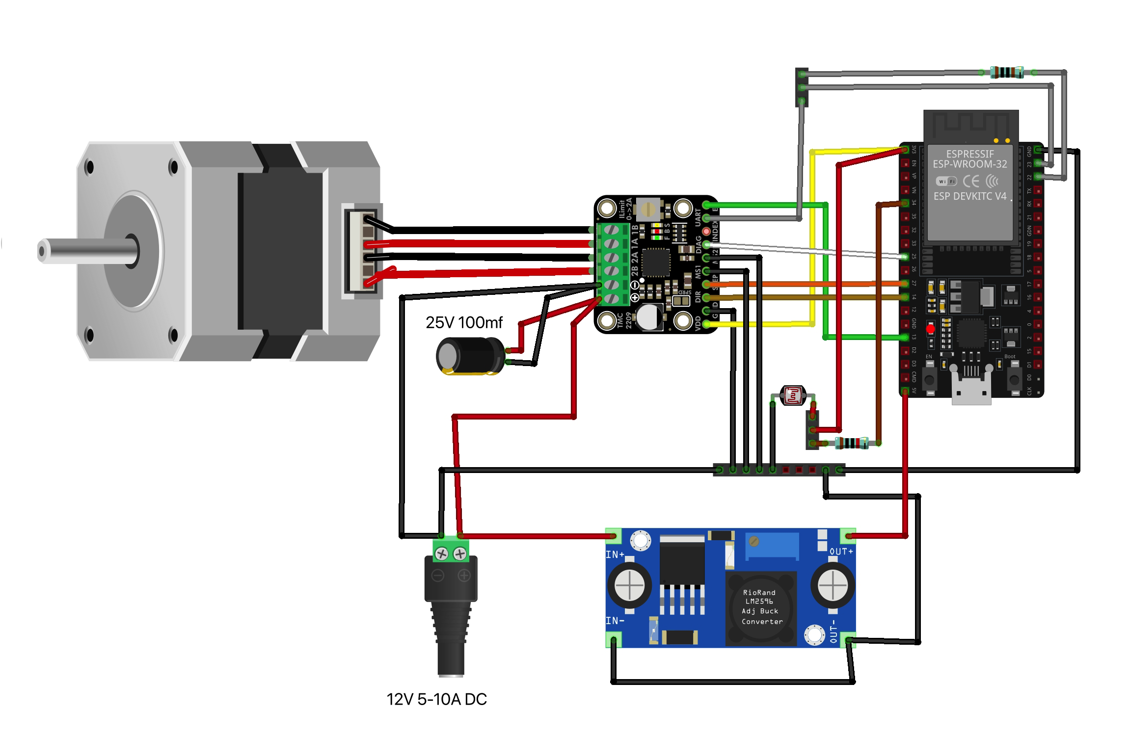
How To>>> Parts, Tools, and Wiring Video <<<
These plastic boxes perfectly fit the Nema 17 stepper motor almost to the point that the motors don't need to be mounted. Find where the blind rod lines up and drill the holes for the shaft and the mounting screws. The hole for the shaft is roughly 1/4 inch and the holes for each of the 4 screws is 1/8 inch.
Mounted with and without the coupling tightened on the motor's shaft.
Tighten the coupling on the blind rod and let the box hang freely to see where it naturally aligns with the window frame. Then drill the L-bracket into the frame and use a level on the top of the box. Once level, drill the holes for 2 machines screws on the box side of the bracket. I used the same M3 screws that the motor mount uses.
MAKE SURE the screws are facing into the box. The inside of the 90 degree bracket should be smooth and flush so the blinds don't catch.
Two of my blinds were 1.5 inches further from my window so I fabricated extensions for the brackets using a stud joint made of galvanized steel.
Again, I secured the custom bracket extensions using the same M3 screws that the Nema 17 uses for mounting.
Before or after building the circuit, back-wire the power supply to each box. Here I splice together a second line to create a power bus along the top of the blinds. The adhesive wire clips and flat white speaker wire, along with the blind covers along the top of the blinds, provide and extremely clean and nearly unnoticeable power cable run.
Solder the 4 PCB connections of the buck converter. I soldered on 3 wires to be soldered to the power supply and ground bus for the power in and ground in and out.
For the power out, I directly soldered a female jumper wire because that wire goes to the 5V pin on the ESP32 board.
Solder the DIAG pin on to the stepper driver. This is easier to do before the heat sink is attached. The other 2 pin connections can be ignored.
The 100mf 25V (to 35V) capacitor should be as close to the driver as possible. Therefore, I soldered it directly into the female jumper wires and covered it with shrink wrap.
The fuse is the first thing to attach to external power. On the other side, join together the 12V power in for the buck converter and the VM supply voltage (with the capacitor inline) to the fuse holder. NOTE you may want to make the fuse holder wires shorter than shown here so there is more space in the box.
Solder the circuit for the UART pin of the driver. The TX pin from the ESP32 will run through a 1k Ω resistor and the RX pin will bypass it to go straight to the UART pin, forming a Y junction. Doing this all with female jumper wires makes the final assembly easier.
Wire up the ESP32 to the driver following the wiring schematic. I used female jumper wires, with the other ends cut off and stripped, on all the pins needing to connect to ground. Then connected them to later solder to the power supply circuit and create a large ground bus. Note the MS1 and MS2 pins need to connect to ground so they aren't left floating signal. It's also recommended to connect both grounds of the driver board even though they are internally connected because the 22 gauge wire offers higher current.
Once the grounds are all connected, solder the entire ground bus together. Not shown here but after the ground bus is together, I then soldered on a 14 AWG cable over the entire bus with a female disconnect crimped on the other end. That disconnect attaches directly to the 12V power coming into the box.
I also added a fuse matching the power supply amperage, 5 or 10 amps, into the power supply line and added disconnects there as well. This will let me unplug the entire project while leaving the back-wiring, around and above the blinds, in tact.
DON'T FORGET to hook up a multimeter and tune the potentiometer on the buck converter to exactly 5V stable for the ESP32 VM power.
Flash the ESP32 using ESPHome web UI. Then upload the code over USB or OTA and navigate to the blind's IP address or local URI. Something like http://blind-right-1.local/ (check the logs).
Attach the wiring harness to the stepper and disconnects to the power supply.
Tune the range of steps from 0 (fully closed) to find the perfect open position. I found my range to be from 13, 000 to 26, 000 steps depending on the size of the window. I used a level on the blinds to find the fully open position.
The web UI for the ESPHome device, which can be accessed directly without Home Assistant, looks like this. Note it's night time in this screenshot so the light level is 0 and the blinds are fully closed.
My Home Assistant dashboard looks like this. The thresholds are for the light sensors so I can tune when I want the blinds to open and close, or set a linear scale with thresholds. I also have the blinds open as sunrise and close at sunset so I added this custom card from HACS to monitor the times.
As a bonus I was able to configure a parallel deployment script that updates all the blinds OTA. Each blind also has their own YAML configuration that override the base settings so it's easy to change variables such as the stall detection threshold (for different levels of blind rod resistance), speed, and the fully open position step count.
Finished Product>>> See Demo Here <<<
Prototype V1. The wire nut was not part of the final version. In the final version every connection is soldered and shrink wrapped.
Photo resistor version. Note the photo resistor is an optional additional sensor but I added one on the two windows near my desk so I can have the blinds open inverse to the amount of light the sensor is receiving.
All 5 blinds boxes, running off one 5A and one 10A power supply draw less than 1W of power at rest. I don't have an accurate measurement of power use while running but considering that they run a handful of times throughout the day and for only about 10 seconds of run time, I assume the draw if extremely low relative to other electronics and appliances.
I have them set to turn off using a wifi outlet after sunset but keeping them on could look cool at night and something to consider around the holidays. Note these look much brighter in the photo than in real life due to camera exposure.
I measured the back voltage on manually turning the blinds. At the fastest speed that I could turn the rod by hand, the stepper only output about 3.5V. The risk to the driver would be at 15+V so it's perfectly safe to manually turn the blinds.
Project (Dining) TableIf you had as much fun as I did, your table should look something like this.
This project was a large undertaking. I spent many evenings fine tuning the code to get the UART and DIAG functionality working correctly. The UART pin on the specific driver that I link to below has a mislabel. It's pin 4, NOT pin 5 that is the UART pin. That issue, and using the right level of resistance and TX / RX configuration cost me quite a few hours to figure out. I wasn't going to give up until I had stall detection and UART working though. Hopefully that all saves you some time.
The code is complex and very low level. Google Gemini and Claude Code helped out a lot in debugging. There is a core issue with just using ESPHome out of the box for UART and stall detection - the timing of the loop. The ESPHome cycle isn't fast enough to detect the motor stall accurately. This took an immense amount of time to figure out how to get right. Even AI wanted to give up more than once but I kept exploring alternative solutions. The final code is C script that interfaces with the ESPHome YAML configuration file to fix the timing and stall detection issue while still providing a seamless interface with Home Assistant. That was the hardest part of the entire project.
Between planning, programming, and building, I estimate the project took about 100 hours. This project guide and code should save about 70 of those hours. Note that estimate is for building 5 blinds. Enjoy!
Pro TipUse a silicone or teflon lubricant on the blind mechanism to smooth out the rotation and make them near-silent. A dry bike chain lubricant works perfectly.
Parts for 5 BlindsHopefully this saves you the days leading up to the project picking out and shopping for all the parts. The only real thing you need to change for your setup is the amperage of the power supplies and how many power supplies are needed for your setup.
>>> Parts, Tools, and Wiring Video <<<
This list is all from Amazon. I did not like having to order from Amazon, and would not recommend it, due to the excessive amount of packaging and plastic waste. Unfortunately, there are no electronics stores near me, or any that I found online, that could offer all of the exact components I needed. If you know of a better option, please let me know.
- 12V 5A Power Supply, AC 120V to DC12V 5.5x2.1mm Jack Converter, 12 Volt LED Driver 60W Adapter Transformer for Strip Lights, Surveillance Cameras, External HDD, Monitor, CCTV (Pack of 1)
- HiFind Premium 14 Gauge Flat Speaker Cable Wire 30 Ft White, OFC Electrical Low Voltage Audio Wire 14/2 AWG, Thin PVC CL2 in Wall Rated Outdoor for Home Theater, Car Stereo, Automotive
- Biaungdo 12 Pcs White Metal Corner Brace, 26 x 26 x 32mm L Shape Shelf Bracket, 90 Degree Right Angle L Brackets Support with Screws for Wood, Shelves, Cabinet, Furniture, 4 Holes
- Teyleten Robot TMC2209 V2.0 Stepper Motor Driver StepStick 2.5A UART Ultra Silent for Nano SKR V1.3/1.4 Ender 3 Control Board 3D Printer Parts Replace A4988 5pcs
- hiBCTR 6 Packs ESP32-DevKitC-32 Development Board modules(ESP-32D, ESP-32 CP2012 USB C with 38 pins), Supporting STA/AP/STA+AP, with WiFi+Bluetooth Dual-core and Type-C Interface.
- LM2596 DC-DC Buck Converter Module, 8 Pack Adjustable Voltage Regulator, 3.2V-46V Input (Recommended ≤40V), 1.25V-35V Output, 3A Max, Step Down Power Supply for Arduino, LED, DIY Projects
- uxcell 5 Pcs Aluminum Alloy Shaft Coupling 5mm to 10mm, Flexible Coupling Motor Connector Joint, Stepper Motor Coupler for CNC Machine & 3D Printer (L25xD19)
- 6 Pack Inline Fuse Holder 12V, Upgraded 12 AWG Waterproof Fuse Holder with 66 Pcs Standard Car Fuses (2A/3A/5A/7.5A/10A/15A/20A/25A/30A/35A/40A), YNZDRWA in Line Fuses Holders 12v for Marine Auto
- 6 Pcs Mini Plastic Boxes, 5'' x 3'' x 1.8'' Small Clear Storage Containers with Locking Lids, Clear Plastic Organizers for Crafts, Stationery, Jewelry, Sewing, Multipurpose Cases for Accessories
- YEJMKJ 5Pack Nema 17 Stepper Motor 2 Phase 1.8° 0.26Nm(36.82oz·in) High Torque Bipolar 26mm 1.1Ω 2.0A 4-Wire Shaft 24mm φ5mm 42 Stepper Motor Cable 1M for 3D Printer DIY Robot CNC Machine
- EDGELEC 120pcs 10cm Dupont Wire Female to Female Breadboard Jumper Wires 3.9 inch 1pin-1pin 2.54mm Connector Multicolored Ribbon Cables DIY Wires Length 10 15 20 30 40 50 100cm Optional
- 50PCS Nylon Spade Quick Disconnect Connectors Kit 22-10 AWG Male and Female Electrical Wire Connectors Kit Electrical Insulated Wire Crimp Cold-Pressed Terminals for Automotive, Electronics
- SZFUDIGO Adhesive Cable Holder Management Wire Clips 50 Pcs White,Suitable for Cables with a Diameter of ≤ 6mm in Cars, Houses, and Offices
- M3 Flat Head Machine Screws and Hex Nuts Kit, 380 Pcs Black Countersunk Head Phillips Screws Bolts Nuts Assortment Kit - M3 x 4mm/ 6mm/ 8mm/ 10mm/ 12mm/ 16mm/ 20mm
- Facmogu 12V 10A Power Supply AC to DC Adapter, AC to DC Converter 100V-240V to 12V 10A 120W, 12 Volts 10 Amps Power Transformer 5.5x2.5mm & 5.5x2.1mm Tip, Desktop Regulated Power Adapter


Comments