


Hardware components | ||||||
| × | 1 | ||||
 |
| × | 1 | |||
| × | 1 | ||||
_ztBMuBhMHo.jpg?auto=compress%2Cformat&w=48&h=48&fit=fill&bg=ffffff) |
| × | 1 | |||
 |
| × | 1 | |||
 |
| × | 1 | |||
 |
| × | 1 | |||
 |
| × | 1 | |||
| × | 1 | ||||
Software apps and online services | ||||||
 |
| |||||
Hand tools and fabrication machines | ||||||
| ||||||
 |
| |||||
This project began as a design challenge when my friend, J.R. Skok (a planetary geologist at the SETI Institute), provided me a bunch of basaltic fabrics to make something fashionable. These fabrics were made of volcanic lava, which were mined, melted, pulled into threads and woven into fabrics. Basalt is the most common rock on Mars but is also found throughout the Earth in places like Hawaii and Iceland and on the volcanoes of most continents. Designing with fabrics made from volcanoes on Earth is a fascinating connection to our planet and a critical step toward learning how to build on other worlds. J.R. has been working with these fabrics for their potential to be made wherever basalt is common, but other fabrics are rare. Maybe one day when humans visit Mars, we'll be using items made of these rocks.
While I was trying to master constructions using these fabrics, I couldn't help but thinking when and why we would ever want to visit Mars. Apart from our scientific curiosity and exploration, could it be caused by in-habitability of the Earth environment? Thus, I embedded an optical dust sensor from DFRobot and used the temperature sensor on Adafruit Circuit Playground Express in the hope to make us be more aware of air pollution and global warming.
Introducing to you, Made of Mars fashion design.
1. Handbag and purse
1.1. Material selectionAlthough I had a vision of the dress, I started making simpler items first to get used to the materials. There are a few different kinds of the basalt rock fabrics. The threads were woven in different ways, creating different touches and stretches of the fabrics. They are all a bit rigid, made of a mildly flexible sort of glass, so the edges tend to fall apart if not protected. Some fabrics are stabilized with aluminum foils. This kind tends to be very good for making stiff structures. Thus, I used this type to make the base of a handbag and a purse. (See description of the fabrics here https://www.madeofmars.com/design ) There are two other kinds of basaltic fabrics I used which will be described later.
I drew and cut out a pattern for a semi-circular bag and sewed the patterns together to get the initial shape. (I didn't use an existing pattern. Just dreamed up some patterns that would give me the correct 3D shape.) Surprisingly, even though the fabric was quite thick and had aluminum foil on one side, it was pretty easy to sew on a normal sewing machine.
Next is the lining. I found some very beautiful mesh-like fabrics with denim decorations on it. They match very well with the color of the basaltic fabrics, which has a dark, golden luster to it.
Then I folded the edges and sewed them inside another piece of fabric. This way, the finishing looks seamless. This other type of fabric is very interesting. The way threads were woven in made the fabric stretchy in one direction and can be very flexible. They come in a belt. The strands of threads can also be separated. I inserted yet another type of basaltic fabric, or rather it's a thin rope, through the gaps between the strands. This rope made up a strap for the bag.
One thing to note is that whenever you cut the fabrics (other than the one with aluminum foil), you need to hold the ends together, otherwise the threads will fall apart. I used plastic tapes to stick the threads together. These were all folded and sewn inside the linings. So the tapes are invisible :)
1.3. EmbellishmentTassels are really in fashion this year (don't know who defines the trends). When I first saw these basaltic fabrics, my first reaction was to combine it with tassels. Because the fabrics look very much like straws. I decorated the bare bag with bright and colorful tassels, fluffs and ribbons.
The first Martian tassel bag was born!
While complexity of a tassel bag was worth pursuing, minimalism is also attractive. In addition, because the dress I had in mind would have fewer colors, I decided to make another purse that would match with the dress better. Here's what I came up with.
The design of this purse fully takes advantage of the different textures of materials. One could put a tablet in it.
2. The dress
Alright, in the above photo you already noticed the unfinished dress in the background. Here's the construction process.
2.1. BaseAs mentioned in my previous project, a basic pattern can be used to guide sizing. Then modify details to make your design. I found a basic tube dress and cut out the fabric based on the right size.
As the belt-type basaltic fabric mentioned above gives really good structure, I wanted to use it to make a prominent collar.
And decorate the whole dress with it.
3. Circuits
Now the fun part.
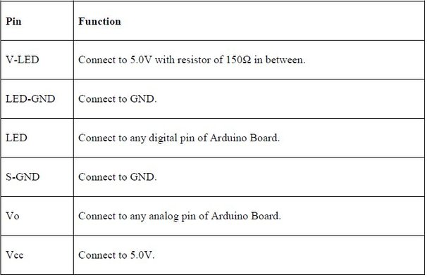
As a common theme in many of my projects, I usually start by testing out the components. For the optical dust sensor, most existing projects are built on Arduino Uno. I referred to this project by mybotic and made sure my circuit behaved in the correct way. (I didn't have a 150 Ohm resistor so I used a 100+47 Ohm in series.)
Then I can replace the Arduino Uno with an Adafruit Circuit Playground Express, because the latter is more wearable and already has a temperature sensor on the board. But before soldering I always test out the circuit first.
The code provided below combines the dust sensing with one of the Circuit Playground examples called "analog_sensors". It can be found in the Adafruit Circuit Playground examples after you download the library. Here to learn how to use Adafruit Circuit Playground Express.
The value of the dust sensor will trigger a buzzing sound at a frequency scaled with the dust reading. Every time the wearer resets the circuit, the buzzer will make a pitch. The colors of the NeoPixels are defined by the temperature reading. This way, the sound and colors are the outputs that alerts the wearer about their environment.
The fabric is see-through and I can leverage that for subtle lighting by putting the Circuit Playground inside. The dust sensor needs to be outside. Therefore, before soldering, the wires should be fed through the fabrics.
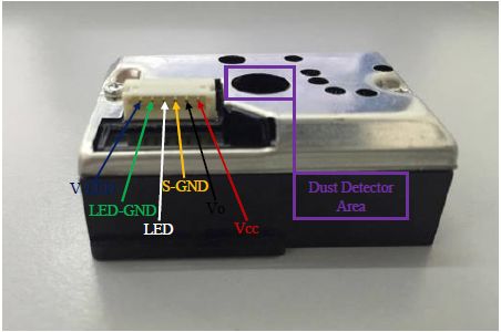
Because this would mean taking off the wires from the board, I came up with a trick to remember which wire goes into which pin without needing to refer to a schematics. I left the color coded clips on and will take one off for soldering at a time, corresponding to the color coded wires.
Use heat shrink tubing to protect the soldered joints. Also do not solder the wires from the dust sensor directly onto the pins. Rather, add a section of wire to each dust sensor wire to compensate the additional length added by the two resistors on one of the wire already.
Bind the cables together with a tape and glue the taped section onto the fabric inside. This will create a stress release so the soldering joints are less likely to break.
Plug in the battery and play!
4. Photography
One more interesting aspect about these design projects is experimenting with photography. J. R. Skok also gave me these cute solar system planets from AstroReality. These are globes that can actually be viewed on AR.
I hope one day I'll make an AR dress and experience flying to Mars.
More photos on www.artbyphysicistkittyyeung.com
Pin connections


Comments