


Hardware components | ||||||
| × | 1 | ||||
Software apps and online services | ||||||
| ||||||
| ||||||
Hand tools and fabrication machines | ||||||
 |
| |||||
I’m using this Macro, which is the same as in previous tutorials. It can be found on this Thingiverse page.
- Make a new file (ctrl + n).
- Save the file (ctrl + s).
- Enter the “Part Design” workbench.
- Go to the Macro menu.
- Click on “Macros”.
- Click on Lego.FCMacro and “Execute”. If you haven’t installed the LEGO macro, take a look at the previous tutorial. You might have to zoom out to see the lego piece (the scroll wheel on the mouse).
- Go to the “Combo view” panel and click on “Lego” object under “labels & Attributes”.
- Click on the “Data” tab at the bottom of the Combo view panel.
- Change the values of units X & Y to 2 and hit enter on your keyboard.
- Change view to see the brick from a side view (The “3” key).
- Click on the side of the brick facing you.
- Click on tasks in the Combo view panel.
- Click on “Create sketch” under “Face tools”.
- Click on the rectangle drawing tool and draw a rectangle in the new sketch. The rectangle should cover the knobs but not the body of the brick.
- Click on the “external geometry” tool.
- Click on the edge of the brick underneath the knobs. A pink edge will appear to show you the imported line from the brick. This is a reference to the brick on which the sketch is drawn.
- Click on the bottom left points of the rectangle and click on the left point of the pink line. Note: To unmark something in FreeCAD, click somewhere outside of the object you are working on.
- Press the “C” on the keyboard or click on the point constraint in the constraint toolbar. Now the the two points should share the same position.
- Click on “Close” in the Tasks tab in the combo view panel.
- Click on the Tasks tab and click on pocket.
- Choose “Through all” in the “Type” drop down menu. If it doesn’t work try ticking the “Reversed” option in the pocket parameters.
The LED we will be using has a diameter of 9.6 mm and has the shape of a circle with flattened sides. We will hollow out the top of the brick to make a holder for the LED. Also, we have to add a box shape to fill out the brick where we will make the holder for the LED.
- Click on the Part Design menu.
- Choose “Create sketch”.
- Enter 2 mm under “Offset” and click on the OK button. The new sketch will begin on zero on the Z-axis, therefore we will add 2 mm to not fill in the bottom of the brick that is going to fit on top of our LEGO bricks.
- Draw a rectangle on the new sketch.
- Click on two of the perpendicular sides of the rectangle.
- Click on the Equal restraint on the restraints toolbar. Now you should have a square.
- Click on one of the side of the square.
- Click on the distance constraint (ctrl + D), enter 15.8 mm and click OK.
- Go to the model tab in the Combo view and click on the feature called “pocket”.
- Hit the spacebar on your keyboard to hide the feature. We do this to make it easier to select point in our sketch.
- Select the two diagonal points in each corner of the square by clicking on them.
- Select the global center point that is located in the middle of the brick.
- Click on the symmetry constraint in the constraint toolbar. The square should now be centered with the brick and the square should be green instead of white.
- Click on the “pocket” feature and hit the spacebar again to show the brick.
- Go to the Task tab and click close.
- Go to the Tasks tab again and click on “Pad”.
- Enter a value of 7.6 mm and click OK.
- Switch to the “Part” workbench.
- Select both the “Pad” and “pocket” objects under the model tab in the combo view. Use the shift key to mark multiple objects.
- Click on the union tool in the boolean toolbar.
- Click on the top of the brick that is now called “Fusion”. This is where we want the cut out to originate.
- Go to the Tasks tab and click on “create sketch”.
- Draw a circle with the starting point on the center origin point.
- Set the radius of the circle by clicking on the circle and then clicking on the radius restraint tool. Enter 5.1 mm in the input menu that pops up.
- Exit the sketch and make the circle into a 6.5 mm deep pocket.
- Click next on the surface next the hole that the circle made and make a new sketch from the Tasks tab.
- Draw a box on top of the circle.
- Click on the edge points that are on the diagonal corners and click on the sketch centerpoint. 3 points in the sketch should be green now.
- Click on the symmetry constraint to center the box with the origin point in the middle. Notice that there are arrows pointing from the points towards the point in the middle.
- Click on either the left or the right vertical side of the box.
- Click in the vertical length restraint and input 4.4 mm (as seen in the picture below).
- Click on the external geometry tool and use it on the left of the brick.
- Click on one of the points on the left side of the box and click on the pink reference line you got from the external geometry tool.
- Click on the “fix a point to a object”constraint to limit the box to the brick.
- Close the sketch.
- Click on pocket in the tasks tab, enter 6.5 mm in the pocket parameters and click OK.
- Select one of the sides of the brick.
- Go to the tasks tab and create a sketch.
- Draw a box.
- Use the external geometry tool on the top of the brick.
- Click on one of the top points of the box and and one of the reference lines points.
- Click on the coincident constraint in the constraints toolbar.
- Click on the left top and bottom point of the box and press the vertical length constraint.
- Enter 4 mm and click OK.
- Close the sketch and choose pocket from the tasks tab.
- Choose “through all” in the pocket parameters under type and press OK.
To compensate for the expanding nature of the plastic we will make the bottom edges of the brick a little bit thinner. To make the brick printable we will make the cylinder on the of the brick touch the print surface when we print it.
- Rotate to see the brick to see the bottom.
- Click on the surface of the cylinder that's on the bottom of the brick. This cylinder is actually not touching the surface if you place it downwards. Therefore we will have to extend it.
- Create a new sketch from the tasks menu.
- Use the external geometry tool to make a reference line from the cylinder's outside.
- Draw a circle and select the center point of circle.
- Also select the center point of the pink reference circle.
- Click on the coincident restraint to center the white circle with the pink.
- Click the outline of the white and pink circles and click on the equal restraint.
- Repeat steps 4 - 9 but with the inside of the cylinder.
- When done, exit the sketch, click pad in the Tasks tab, enter 0.375 mm under length and click OK.
- Click on the face of the outer lip of the brick and start a new sketch from the tasks tab.
- Use the external geometry tool and click on the outer and inner edges of the lip.
- Draw a square and select the top left point of the square.
- Select the top left point on the inner pink box.
- press the “C” key on your keyboard or click on the coincident restraint in the restraints toolbar.
- Do the same with the bottom right point of the white box.
- Draw another box. Draw it in between the two pink boxes and use the equal restraint to make the side of the box equal in length.
- Draw a small box from the top left pink reference point to the new white box's top left corner point. Make sure that the new box is connected with both the reference lines and the white box. If you missed it, use the coincidence constraint to connect them.
- Click on two of the adjacent perpendicular lines in the new small box.
- Click on the equal restraint to make the line the same length.
- Use the horizontal or vertical length to set the length between the other reference line and the outer white box. Set the distance to 1.1 mm.
- The last thing we do before exiting the sketch is select the small dummy box and click on the construction lines tool. This is to make sure that this box is only meant for help with the construction and not make any changes itself.
- Exit the sketch and click on pocket in the tasks tab and enter 2 mm in the pocket parameters.
- And you are done with the model.
Remember to have a clean surface. Wipe it with acetone if you are using blue painters tape and if you are using hairspray, remove old spray and apply a new uniform coat.
In general you can use a lower temperature (around 195 or 200 Celsius) when printing smaller objects. A lower speed also helps out, both to make it possible to extrude the thicker less fluid plastic (due to the lower temperature) and to make sure the previous layers have enough time to cool down.
To make these alterations in the settings in Slic3r:
- Open Slic3r.
- Load the settings from the “Load config” option in the “File” menu.
- Click on the “Print settings” tab.
- Click on “Speed” in the white box on the left side of the Slic3r window.
- Under “speed for print moves” change the following parameters to the following values: Perimeters: 40 mm/s Small perimeters: 30 mm/s External perimeters: 35 mm/s Infill: 50 mm/s Solid infill: 35 mm/s Top solid: 30 mm/s
- Click on the “Filament settings” tab.
- Click on “Filament” in the white box on the left side in the Slic3r window.
- Change these two parameters under “temperature” to the following value: Extruder First layer: 200 C, Extruder Other layers: 195 C.
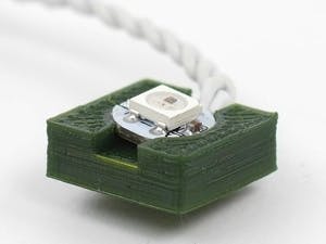
In the pictures below you can see my results:
kengdahl
 Arduino_Scuola


Comments