


Hardware components | ||||||
 |
| × | 1 | |||
_ztBMuBhMHo.jpg?auto=compress%2Cformat&w=48&h=48&fit=fill&bg=ffffff) |
| × | 1 | |||
 |
| × | 1 | |||
| × | 1 | ||||
Software apps and online services | ||||||
 |
| |||||
 |
| |||||
Hand tools and fabrication machines | ||||||
 |
| |||||
 |
| |||||
From the beginning, I knew I needed to incorporate a retro toy into my project. I had considered the Tickle Me Elmo, as those re-entered production a few years ago, but didn't think I could do the project justice under my time constraints. I first discovered the stylophone after watching a 7 second video of it on YouTube, and saw that it could be had for less than $25 USD on Amazon! It went downhill from there.
First StepsUpon receiving my very own stylophone, I took the included male to male 3.5mm audio cable (and three not-so-included AA batteries) and scoped the output signal with one hand holding the wires together and the other holding the stylus to the keypad.
Since the stylophone outputs a mono signal, I used the tip (T) as the input and the sleeve (S) as the ground (R stands for ring, by the way).
The basic stylophone has a switch for 3 sound profiles, a vibrato switch, a power switch, a volume dial, and a tuning knob. I'd recommend using profile 1 at max volume and no vibrato, and all results below use these settings. When in tune, the stylophone's lowest note is A (110Hz), and the highest note is E (329.63 Hz). The output of the stylophone has a minimum voltage from anywhere from -1.7 V to -100 mV as the stylophone turns on ("warms up" so to speak) and a peak voltage of anywhere from 1.7 V to 3.5 V. Since the TI MSP430G2553 cannot read negative voltages and the Uno can only read negative voltages if you shift the reference voltage, I decided to build a gain and shift circuit using a TI LM741 op amp.
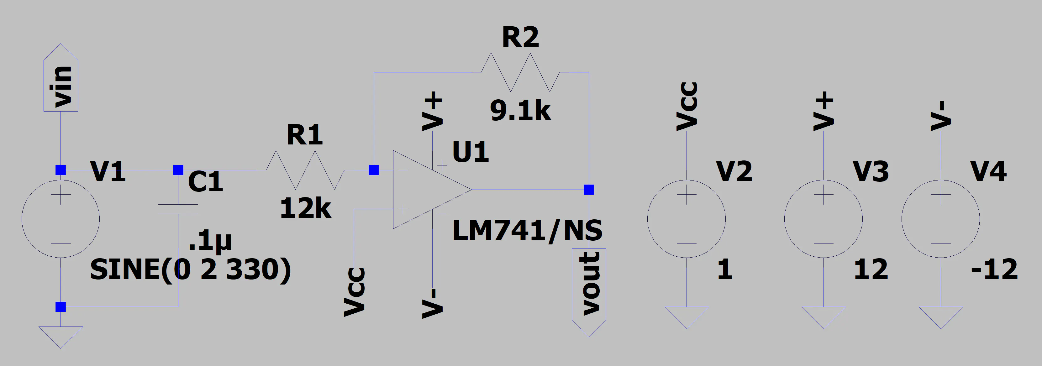
The CircuitA simple circuit can be built to shift [-2, 2] V to [0, 4[ V and apply a gain to get the output [0, 3] V.
The non-inverting input can be controlled with the 3.3 V supply from the MSP430G2553 and a 10k potentiometer. R1 and Rf in the diagram were chosen to be 9.1 kOhm and 12 kOhm to achieve the 9.1k/12k ≅ 3/4 gain. Somewhat large resistors were also chosen to limit the amount of current flowing. With this in mind, I designed and simulated the circuit in LTSpice (which you can download for free here).
An accurate simulation like this is possible since TI thankfully provides a SPICE model for many of their parts. (You can download the LM741.mod here). The simulations give the expected shift from [-2, 2] V to [0, 3.3] V, so time to build the circuit!
Building the CircuitThe only parts used in the circuit were a 9.1k and 12k Ohm resistors, a 0.1μ Farad capacitor, a 10k potentiometer, the TI LM741, a 3.5mm audio jack, and some wires.
After soldering up the circuit, it was powered using a +12/-12 V DC power supply and the 3.3 V off the MSP430G2553. Giving an input sine wave of 4 V peak-to-peak from a function generator yielded exactly what I wanted to see.
Now giving the input from the stylophone and adjusting the potentiometer shift...
You'll notice that the high note (E 329.63 Hz) is much more compact than the low note (A 110 Hz) -- by definition. This creates problems with sampling that will be explained later.
The MSP430G2553 (Master)The role of the MSP4302553 is to sample the audio signal, send it to the arduino, and based on the received information, move the servo. The ADC10 and Timer A0 is set up to sample at 8kHz.
// Init ADC10
// Control Register 0
ADC10CTL0 = SREF_0; // Vr+ = Vcc and Vr- = Vss (default)
ADC10CTL0 += ADC10SHT_1; // 8 X ADC10CLKs
// ADC10SR: 2000 ksps (default)
// REFOUT: reference output off (default)
// REFBURST: continuous (default)
// MSC: single conversion mode (default)
// REFON: reference generator off (default)
ADC10CTL0 += ADC10ON; // ADC10 On
ADC10CTL0 += ADC10IE; // interrupt enabled
// Control Register 1
ADC10CTL1 = INCH_3; //input channel A3 (default)
ADC10CTL1 += SHS_0; // sample and hold source ADC10SC (default)
// ADC10DF: straight binary data format (default)
ADC10CTL1 += ADC10DIV_0; // Clock divider, try values and check noise
ADC10CTL1 += ADC10SSEL_0; // clock source ADC10SC
ADC10CTL1 += CONSEQ_0; // Single channel single conversion
// analog enable control register 0
ADC10AE0 = 8; // Enable A3 as ADC channel
Pin 1.4 is made (arbitrarily) the slave select and SPI is initialized
// Initialize Port 1, P1.0 LED, P1.4 SS
P1SEL &= ~(BIT0 + BIT4); // P1.0 and P1.4 GPIO
P1SEL &= ~(BIT0 + BIT4); // P1.0 and P1.4 GPIO
P1REN &= ~(BIT0 + BIT4); // P1.0 and P1.4 Resistor disabled
P1DIR |= BIT0 + BIT4; // Set P1.0 and P1.4 to output direction
P1OUT &= BIT4; // Initially set P1.4/SS high
// Port 1 SPI pins, P1.5 SCLK, P1.6 MISO, P1.7 MOSI
P1SEL |= BIT5 + BIT7 + BIT6; // Secondary Peripheral Module Function for P1.5-1.7
P1SEL2 |= BIT5 + BIT7 + BIT6; // Secondary Peripheral Module Function for P1.5-1.7
// Polarity and SCLK for SPI
UCB0CTL0 = UCCKPH + UCCKPL; // first edge: data capture, following edge: data update , SCLK inactive state High
// Initialize SPI
UCB0CTL0 |= UCMSB + UCMST + UCSYNC + UCMODE_0; // MSB first, master, 3-pin, 8-bit synchronous
UCB0CTL1 = UCSSEL_2 + UCSWRST; // SMCLK, enable SW Reset
// bit rate: SMCLK/x=SCLK
// smclk same as arduino uno (16 Mhz)
UCB0BR0 = 32; // low byte, divide by
// 4 divider or greater, 8 and 16 causes issues, 32 seems okay
UCB0BR1 = 0; // same as 1 divider, high byte
UCB0CTL1 &= ~UCSWRST; // **Initialize USCI state machine**
IFG2 &= ~UCB0RXIE; // Clear RX interrupt flag in case it was set during init
IE2 |= UCB0RXIE; // Enable USCI0 RX interrupt
Port 2 is setup to use TA1 and TA2 pins to create a PWM signal to control the servos.
// Init Port 2
// setup P2.1 with Timer1_A3.TA1 and P2.4 with Timer1_A3.TA2
P2DIR |= 0x12;
P2SEL |= 0x12;
P2SEL2 = 0;
Stepping back, lets talk about SPI.
SPIThere's a lot to it, but it boils down to a communication interface specification created by Motorola in the 1980s that works as a two way street. There are four major lines that the master (MSP430G2553) and the slave (Uno) need to share: SCLK, MISO, MOSI, and SS. The SCLK (Serial Clock) is generated by the master so that communication stays in sync. MISO (Master In Slave Out) and MOSI (Master Out Slave In are the two sides of the street that tell which direction traffic is travelling (sometimes called SOMI and SIMO). The SS (Slave Select) tells when the slave should listen to the master, and when to ignore it. This allows one master to have multiple slaves without causing miscommunication. There are different ways to configure SPI, but the settings I've chosen (as specified in the code above) look like this.
This diagram can be found on page 448 of the MSP430x2xx Family User's Guide.
Arduino Uno (Slave)Arduino proves a library to make SPI communication easy but is only for making Arduino the master (go figure).
pinMode(MISO, OUTPUT);
// turn on SPI with interrupts, slave mode, msbit first
// clock idle when high, sample on falling edge of clock
SPCR = _BV(SPE) + _BV(SPIE) + _BV(CPOL) +_BV(CPHA);
/*
* SPIE - Enables the SPI interrupt when 1
* SPE - Enables the SPI when 1
* DORD - Sends data least Significant Bit First when 1, most Significant Bit first when 0
* MSTR - Sets the Arduino in master mode when 1, slave mode when 0
* CPOL - Sets the data clock to be idle when high if set to 1, idle when low if set to 0
* CPHA - Samples data on the falling edge of the data clock when 1, rising edge when 0
* SPR1 and SPR0 - Sets the SPI speed, 00 is fastest (4MHz) 11 is slowest (250KHz)
*
*/
The setup only requires two lines of code, but most of the difficulty in the communication lies in getting the Uno to cooperate as the slave. The Uno and the MSP430G2553 both operate at 16Mhz, but the MSP430G2553 can communicate through SPI faster by setting the baud rate control register with a smaller divider (UCB0BRx). The Uno requires at least a 4 divider (4 Mhz) but I found occasional mis-transmissions (0x1234 becomes 0x3400) until a 32 divider (500 kHz). One of the reasons I chose to make the MSP430G2553 the master is due to the ADC taking a 10 bit sample, whereas the Uno can only take 8 bit samples. More is better here as it gives more resolution, meaning that the MSP430G2553 may be able to see a difference in 1 mV whereas the Uno may not. While SPI between these two devices sends 8 bits at a time, one can simply send 2 sets of 8 bits to get the MSP430G2553's 10 bit value across. The only issue is making sure the slower Arduino doesn't fall behind.
The Rest of the OwlThe original intent was to use FFT or pitch detection library on the Uno, but that only made things slower. Ultimately, since I knew the shape (one rising edge and one falling edge per cycle) of the signal coming from the stylophone, I took a simpler and faster approach. I simply waited for the average of the last 4 samples to be greater than a threshold when the previous average was less than the threshold. This told me I had triggered on the rising edge. Then I counted how long until this happened again and stored it. Then I'd simply take the median of the last 10 counts/periods to filter out any outliers. This happens instantaneously and allows for the servo to react in real time.
The servo is simply moved by changing the duty cycle of the PWM signal on the MSP430G2553. For example:
TA1CCR2 = 2100; TA1CCR1 = 2100;
I may try to refine the code so that the servo is more stable at high frequencies at a later time. Although the Nyquist sampling criterion tells us that the sampling frequency only needs to be double the highest desired recoverable frequency, this faster method doesn't use the FFT or any type of interpolation, so the sampling frequency simply isn't fast enough.
The code for the TI MSP430G2553 and the Arduino is attached if you'd like to take a look at it. A video of the final product is also there.


Comments