

Hardware components | ||||||
 |
| × | 1 | |||
 |
| × | 1 | |||
| × | 1 | ||||
 |
| × | 1 | |||
 |
| × | 1 | |||
Software apps and online services | ||||||
 |
| |||||
| ||||||
| ||||||
| ||||||
Hand tools and fabrication machines | ||||||
 |
| |||||
Quick heads-up: the above video was filmed during a demo session, so it's a bit loud.
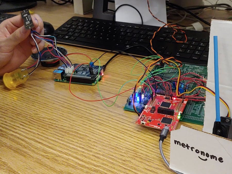
The hardwareIt's often useful to use an expansion board for more functionality to take on specific tasks. Fortunately, the Ras Pi has plenty of available "hardware attached to top" (HAT) on the market. These HATs plug into the Ras Pi's GPIO pins and have to conform with the Raspberry Pi Foundation's standards on physical dimensions and software integration. This project uses the Google AIY Voice HAT, as well as the other hardware poached from the Google AIY Voice Kit (V1). These kits retailed for quite a bit, but can be had (at the time of writing) on eBay for $10 and less. This gives all the hardware we need and reduce integration troubles.
Of course, we can't foget the MSP432P401R. While the Ras Pi excels at being a good value for its wide applicability and relative computing power, it does suffer in GPIO and controlling other hardware. (Which is why the market for Ras Pi HATs is so plentiful!). The MSP432 is a great little microcontroller with many multiple times the number of pins (for the 100 pin PZ package) and key features like a 14 bit ADC. This is before we take general positives into consideration, like power efficiency and timing critical operations. It is important to note that the two serve different purposes, and putting the two together allows for a whole new world of possibilities.
Google AssistantGiven that we already had the Google AIY Voice hardware, it was decided to use the Google Assistant API for reliable voice recognition. Many of us have had assistants like Siri or Bixby on our phones mishear us, and rather than run an even simpler voice recognizer, we figured that Google assistant would be one of the best choices.
You can start with the Google AIY images of raspbian found on their Github (if you're using the AIY Voice HAT). Otherwise, you can use a clean installation of raspbian/linux distro of your choice and simply clone the Python repo after installation. In order to call the Google Assistant API, you will need to set up Google Cloud Credentials. Instructions to do so can be found here.
In retrospect, since the goal of calling the Google Assistant API was to get speech-to-text, I would look into other solutions, such as the SpeechRecognition Python library. The SpeechRecognition library acts as a wrapper for several APIs, such as Microsoft Bing Speech, Google Cloud Speech, and IBM Speech to Text. Google Assitant was used instead of Google Cloud Speech simply because the former allows for free experimental testing while the latter requires billing. The SpeechRecongition library also supports Google's Web Speech API, which was developed for browsers and doesn't even require a any of the above API key setup. (If only we had known earlier... But having the Google Assistant to tell me how many hours I've been in lab is fun too!)
DialogflowDialogflow is a Google owned service that uses machine learning to process natural language conversations. A project is created in Dialogflow to house all the "intents". Each intent, as the name implies, separates what we want done. Thus, our intents include turning on a specific LED, turning on a specified number of LEDs, setting the metronome to a specified BPM, and more. The beauty of using something like Dialogflow is that with some training phrases, it can tell the difference between "turn on three LEDs" and "turn on LED three". These are commands that a person would naturally say and be able to distinguish, but a computer would generally have a harder time with.
The dialogflow Python library was installed (specifically using dialogflow_v2) and passes on the text pulled from the Google Assistant library. In order to use the Dialogflow API, you'll need to set up authentication keys again, instructions for which can be found here. (Dialogflow V2 was used as Dialogflow V1 is scheduled for shutdown).
The setup python code might look something like this:
DIALOGFLOW_PROJECT_ID = 'your-project-id'
DIALOGFLOW_LANGUAGE_CODE = 'en-US'
os.environ["GOOGLE_APPLICATION_CREDENTIALS"] = os.path.expanduser('~/dialogflow.json')
SESSION_ID = 'hackster-io'
session_client = dialogflow.SessionsClient()
session = session_client.session_path(DIALOGFLOW_PROJECT_ID, SESSION_ID)
and the processing code may look like this:
text_to_be_analyzed = "hello hackster io"
text_input = dialogflow.types.TextInput(text=text_to_be_analyzed, language_code=DIALOGFLOW_LANGUAGE_CODE)
query_input = dialogflow.types.QueryInput(text=text_input)
response = session_client.detect_intent(session=session, query_input=query_input)

print(response.query_result.parameters.values())
print(response.query_result.parameters.keys())
print(response.query_result.parameters.items())
print("Query text:", response.query_result.query_text)
print("Detected intent:", response.query_result.intent.display_name)
print("Detected intent confidence:", response.query_result.intent_detection_confidence)
print("Fulfillment text:", response.query_result.fulfillment_text)This all is great on the Ras Pi but needs to get to the MSP432 somehow. There's a lot to it, but I2C is a communication protocol created by then Philips in the 1980s. There are two major lines (and GND) that the Ras Pi and the MSP432 need to share, the data line SDA and the clock line SCL. Since I2C is sychronous, it relies on the clock to keep everyone together. Also, as I2C is half-duplex, data can only move one way at a time. Imagine a road under construction with only one lane open and a person in a high-vis jacket directing traffic. The details won't be covered, but a sample timing diagram is shown below.
This diagram can be found on page 961 MSP432P4xx User Guide.
On the Ras Pi, the python library smbus2 was used to handle the i2c operations. The I2C setup may look like this:
channel = 1
address = 0x25
# Initialize I2C (SMBus)
bus = smbus.SMBus(channel)
From the Ras Pi's perspective, it wanted to send 3 bytes and receive one byte back, so the following code was developed.
TXData = [0x00, 0x00, 0x00]
RXData = [None] * 1
num_tx_bytes = len(TXData)
num_rx_bytes = len(RXData)
def next_i2c():
    global TXData, RXData, num_tx_bytes, num_rx_bytes
    for i2c_idx in range(num_tx_bytes):
        bus.write_byte(address, TXData[i2c_idx])
    for i2c_idx in range(num_rx_bytes):
        RXData[i2c_idx] = bus.read_byte(address)
    print(TXData[0], (TXData[1]<<8)|TXData[2], RXData[0])
And from the MSP432's perspective, something similar was written in C.
void EUSCIB0_IRQHandler(void)
{
    uint_fast16_t i2c_status = MAP_I2C_getEnabledInterruptStatus(EUSCI_B0_BASE);

    if((i2c_status & EUSCI_B_I2C_RECEIVE_INTERRUPT0) && (UCB0IE & 0x1)){
        RXcount++;
        RXData[i2c_index] = MAP_I2C_slaveGetData(EUSCI_B0_BASE);
        i2c_index++;
        MAP_I2C_clearInterruptFlag(EUSCI_B0_BASE, EUSCI_B_I2C_RECEIVE_INTERRUPT0|EUSCI_B_I2C_TRANSMIT_INTERRUPT0);
        if (i2c_index == NUM_OF_RX_BYTES){
        TXData[0] = RXData[0];
        i2c_index = 0;
        MAP_I2C_disableInterrupt(EUSCI_B0_BASE, EUSCI_B_I2C_RECEIVE_INTERRUPT0);
        MAP_I2C_enableInterrupt(EUSCI_B0_BASE, EUSCI_B_I2C_TRANSMIT_INTERRUPT0);
        i2c_int16 = (RXData[1]<<8)|(RXData[2]);
        state = RXData[0];
        }
    }

    if((i2c_status & EUSCI_B_I2C_TRANSMIT_INTERRUPT0) && (UCB0IE & 0x2)){
        TXcount++;
        MAP_I2C_slavePutData(EUSCI_B0_BASE, TXData[i2c_index]);
        i2c_index++;
        MAP_I2C_clearInterruptFlag(EUSCI_B0_BASE, EUSCI_B_I2C_TRANSMIT_INTERRUPT0); // only clear Transmit
        if (i2c_index == NUM_OF_TX_BYTES){
        i2c_index = 0;
        MAP_I2C_disableInterrupt(EUSCI_B0_BASE, EUSCI_B_I2C_TRANSMIT_INTERRUPT0);
        MAP_I2C_enableInterrupt(EUSCI_B0_BASE, EUSCI_B_I2C_RECEIVE_INTERRUPT0);
        }
    }
}This is another section that will stay brief -- TI has lots of great examples of how to use everything like I2C, GPIO, ADC, SPI, UART, PWM, and more on their website. Additionally, the doccumentation for the MSP432 Simplelink SDK can be found here.
A switch statement was used for the MSP432 to determine what to do, with the state being determined by the information sent over through I2C. Here's an example of one of the LED cases:
case 0x21: // turn off all leds
    MAP_GPIO_setOutputLowOnPin(GPIO_PORT_P4, PIN_ALL8);
    break;
case 0x31: // turn on a specific led
{
    int led_num = i2c_int16;
    if (led_num < 1) led_num = 1;
    else if (led_num > 8) led_num = 8;
    P4OUT = 0b1<<(led_num-1);
    break;
}
And here's an example of the metronome case:
case 0x61:
{
    TA0CCR3 = (int)(((long)TA0CCR0*69L)/1000L);
    int bpm = i2c_int16;
    if (bpm > 300) bpm = 300;
    else if (bpm < 1) bpm = 1;
    beats_period = (int)(60000L/(long)bpm); //ms
    if ((timecheck%beats_period) == 0) state = 0x62;
    break;
}
case 0x62:
    TA0CCR3 = (int)(((long)TA0CCR0*79L)/1000L);
    if ((timecheck%beats_period) == 0) state = 0x61;
break;I may want to try one of the other voice recognition APIs, like Microsoft's, or to simplify the setup process by using the Google Web Speech API. Also, of course there's much more that the MSP432 can do, and many more complex tasks to tackle. Cases can be added in Dialogflow and the code can be adjusted so that the MSP432 can perform more tasks. The hard part is thinking of novel ideas to test out.
All in all, I was pleased at how well this all worked. Most importantly to me, everything worked reliably and consistently. If nothing more, this serves as a proof-of-concept of what can be done, and hopefully this guide is easy enough to follow and explains how some of the amazing IoT projects on the web are done.


Comments