

Hardware components | ||||||
| × | 1 | ||||
| × | 1 | ||||
| × | 1 | ||||
| × | 1 | ||||
| × | 1 | ||||
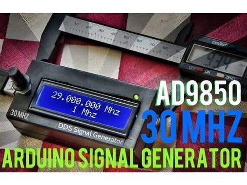
A Precession Signal generator can be made using an Arduino and DDS synthesizer (AD9850), and is the world's first and smallest portable signal generator build. You can make decent 0 -30 MHZ frequency signal generator for only 12$. If you are a pro over-clocker, then 40MHZ for the same price. AD9850 works on DDS (direct digital synthesis) which can generate analog waveforms with digital input. Here I used an Arduino Pro Mini to control the DDS board and Hitachi HD 44780 LCD display (16×2 LCD) to display current frequency and change steps. This signal generator runs on USB 5V and consumes 270 mA max! So you can install a battery pack inside it and make it a standalone system if you want. It's a great project for beginners and will give you a lot of satisfaction, as well as save you hundreds of dollars! You will need a frequency generator if you are an amateur radio guy or hobbyist or professional electronics guy.
Step 1: Get the PartsHere's the parts you will need:
- 16×2 LCD Display (Hitachi HD 44780)
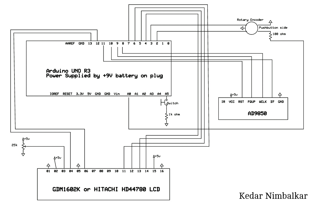
Connect all components as shown in the above schematics.
Step 3: Watch the Full TutorialThe code and schematics can found here or below this tutorial.
Step 4: Output ResponseThe output response is the output waves you get at different frequencies. Here are a few scope shots to get an idea of how well it is.
- 1MHZ
- 10MHZ
- 20 MHZ
- 30 MHZ
/*
Main code by Richard Visokey AD7C - www.ad7c.com
Revision 2.0 - November 6th, 2013
*/

// Include the library code
#include <LiquidCrystal.h>
#include <rotary.h>
#include <EEPROM.h>

//Setup some items
#define W_CLK 8   // Pin 8 - connect to AD9850 module word load clock pin (CLK)
#define FQ_UD 9   // Pin 9 - connect to freq update pin (FQ)
#define DATA 11   // Pin 11 - connect to serial data load pin (DATA)
#define RESET 10  // Pin 10 - connect to reset pin (RST)
#define pulseHigh(pin) {digitalWrite(pin, HIGH); digitalWrite(pin, LOW); }
Rotary r = Rotary(2,3); // sets the pins the rotary encoder uses.  Must be interrupt pins.
LiquidCrystal lcd(12, 13, 7, 6, 5, 4); // I used an odd pin combination because I need pin 2 and 3 for the interrupts.
int_fast32_t rx=0000000; // Base (starting) frequency of VFO.  This only loads once.  To force load again see ForceFreq variable below.
int_fast32_t rx2=1; // variable to hold the updated frequency
int_fast32_t increment = 10; // starting VFO update increment in HZ.
int_fast32_t iffreq = 0000000; // Intermedite Frequency - Amount to subtract (-) from base frequency. ********************************************
int buttonstate = 0;
int buttonstate2 = 0;
int GoIF = 1;
String hertz = "10 Hz";
int  hertzPosition = 5;
byte ones,tens,hundreds,thousands,tenthousands,hundredthousands,millions ;  //Placeholders
String freq; // string to hold the frequency
int_fast32_t timepassed = millis(); // int to hold the arduino miilis since startup
int memstatus = 1;  // value to notify if memory is current or old. 0=old, 1=current.


int ForceFreq = 1;  // Change this to 0 after you upload and run a working sketch to activate the EEPROM memory.  YOU MUST PUT THIS BACK TO 0 AND UPLOAD THE SKETCH AGAIN AFTER STARTING FREQUENCY IS SET!


void setup() {
  pinMode(A0,INPUT); // Connect to a button that goes to GND on push
  pinMode(A5,INPUT); // IF sense **********************************************
  digitalWrite(A0,HIGH);
  digitalWrite(A5,HIGH);
  lcd.begin(16, 2);
  PCICR |= (1 << PCIE2);
  PCMSK2 |= (1 << PCINT18) | (1 << PCINT19);
  sei();
  pinMode(FQ_UD, OUTPUT);
  pinMode(W_CLK, OUTPUT);
  pinMode(DATA, OUTPUT);
  pinMode(RESET, OUTPUT);
  pulseHigh(RESET);
  pulseHigh(W_CLK);
  pulseHigh(FQ_UD);  // this pulse enables serial mode on the AD9850 - Datasheet page 12.
  lcd.setCursor(hertzPosition,1);
  lcd.print(hertz);

  // Load the stored frequency
  if (ForceFreq == 0) {
    freq = String(EEPROM.read(0))+String(EEPROM.read(1))+String(EEPROM.read(2))+String(EEPROM.read(3))+String(EEPROM.read(4))+String(EEPROM.read(5))+String(EEPROM.read(6));
    rx = freq.toInt();
  }
}

void loop() {
  // Update the display and frequency if the new Freq NEQ the old Freq
  if (rx != rx2){
        showFreq();
        sendFrequency(rx);
        rx2 = rx;
      }

  // Rotate through the rate of tuning as you hold down the button
  buttonstate = digitalRead(A0);
  if(buttonstate == LOW) {
        setincrement();
    };

  // Check for PIN low to drive IF offset Freq
  buttonstate = digitalRead(A5);
    if (buttonstate != buttonstate2){
        if(buttonstate == LOW) {
              lcd.setCursor(15,1);
              lcd.print(".");
              GoIF = 0;
              buttonstate2 = buttonstate;
              sendFrequency(rx);
          }
        else{
            lcd.setCursor(15,1);
            lcd.print(" ");
            GoIF = 1;
            buttonstate2 = buttonstate;
            sendFrequency(rx);
          };
    };

    // Write the frequency to memory if not stored and 2 seconds have passed since the last frequency change.
    if(memstatus == 0){
      if(timepassed+2000 < millis()){
        storeMEM();
        }
      }

 }


// Interrupt routine to catch the rotary encoder
ISR(PCINT2_vect) {
  unsigned char result = r.process();
  if (result) {
    if (result == DIR_CW){rx=rx+increment;}
    else {rx=rx-increment;};
      if (rx >=30000000){rx=rx2;}; // UPPER VFO LIMIT
      if (rx <=0000000){rx=rx2;}; // LOWER VFO LIMIT
  }
}

// frequency calc from datasheet page 8 = <sys clock> * <frequency tuning word>/2^32
void sendFrequency(double frequency) {
  if (GoIF == 1){frequency=frequency-iffreq;}; //If pin = low, subtract the IF frequency.
  int32_t freq = frequency * 4294967295/125000000;  // note 125 MHz clock on 9850.  You can make 'slight' tuning variations here by adjusting the clock frequency.
  for (int b=0; b<4; b++, freq>>=8) {
    tfr_byte(freq & 0xFF);
  }
  tfr_byte(0x000);   // Final control byte, all 0 for 9850 chip
  pulseHigh(FQ_UD);  // Done!  Should see output
}
// transfers a byte, a bit at a time, LSB first to the 9850 via serial DATA line
void tfr_byte(byte data)
{
  for (int i=0; i<8; i++, data>>=1) {
    digitalWrite(DATA, data & 0x01);
    pulseHigh(W_CLK);   //after each bit sent, CLK is pulsed high
  }
}

void setincrement(){
  if(increment == 10){increment = 50; hertz = "50 Hz"; hertzPosition=5;}
  else if (increment == 50){increment = 100;  hertz = "100 Hz"; hertzPosition=4;}
  else if (increment == 100){increment = 500; hertz="500 Hz"; hertzPosition=4;}
  else if (increment == 500){increment = 1000; hertz="1 Khz"; hertzPosition=6;}
  else if (increment == 1000){increment = 2500; hertz="2.5 Khz"; hertzPosition=4;}
  else if (increment == 2500){increment = 5000; hertz="5 Khz"; hertzPosition=6;}
  else if (increment == 5000){increment = 10000; hertz="10 Khz"; hertzPosition=5;}
  else if (increment == 10000){increment = 100000; hertz="100 Khz"; hertzPosition=4;}
  else if (increment == 100000){increment = 1000000; hertz="1 Mhz"; hertzPosition=6;}
  else{increment = 10; hertz = "10 Hz"; hertzPosition=5;};
   lcd.setCursor(0,1);
   lcd.print("                ");
   lcd.setCursor(hertzPosition,1);
   lcd.print(hertz);
   delay(250); // Adjust this delay to speed up/slow down the button menu scroll speed.
};

void showFreq(){
    millions = int(rx/1000000);
    hundredthousands = ((rx/100000)%10);
    tenthousands = ((rx/10000)%10);
    thousands = ((rx/1000)%10);
    hundreds = ((rx/100)%10);
    tens = ((rx/10)%10);
    ones = ((rx/1)%10);
    lcd.setCursor(0,0);
    lcd.print("                ");
   if (millions > 9){lcd.setCursor(1,0);}
   else{lcd.setCursor(2,0);}
    lcd.print(millions);
    lcd.print(".");
    lcd.print(hundredthousands);
    lcd.print(tenthousands);
    lcd.print(thousands);
    lcd.print(".");
    lcd.print(hundreds);
    lcd.print(tens);
    lcd.print(ones);
    lcd.print(" Mhz  ");
    timepassed = millis();
    memstatus = 0; // Trigger memory write
};

void storeMEM(){
  //Write each frequency section to a EPROM slot.  Yes, it's cheating but it works!
   EEPROM.write(0,millions);
   EEPROM.write(1,hundredthousands);
   EEPROM.write(2,tenthousands);
   EEPROM.write(3,thousands);
   EEPROM.write(4,hundreds);
   EEPROM.write(5,tens);
   EEPROM.write(6,ones);
   memstatus = 1;  // Let program know memory has been written
};
/* Rotary encoder handler for arduino. v1.1
 *
 * Copyright 2011 Ben Buxton. Licenced under the GNU GPL Version 3.
 * Contact: bb@cactii.net
 *
 * A typical mechanical rotary encoder emits a two bit gray code
 * on 3 output pins. Every step in the output (often accompanied
 * by a physical 'click') generates a specific sequence of output
 * codes on the pins.
 *
 * There are 3 pins used for the rotary encoding - one common and
 * two 'bit' pins.
 *
 * The following is the typical sequence of code on the output when
 * moving from one step to the next:
 *
 *   Position   Bit1   Bit2
 *   ----------------------
 *     Step1     0      0
 *      1/4      1      0
 *      1/2      1      1
 *      3/4      0      1
 *     Step2     0      0
 *
 * From this table, we can see that when moving from one 'click' to
 * the next, there are 4 changes in the output code.
 *
 * - From an initial 0 - 0, Bit1 goes high, Bit0 stays low.
 * - Then both bits are high, halfway through the step.
 * - Then Bit1 goes low, but Bit2 stays high.
 * - Finally at the end of the step, both bits return to 0.
 *
 * Detecting the direction is easy - the table simply goes in the other
 * direction (read up instead of down).
 *
 * To decode this, we use a simple state machine. Every time the output
 * code changes, it follows state, until finally a full steps worth of
 * code is received (in the correct order). At the final 0-0, it returns
 * a value indicating a step in one direction or the other.
 *
 * It's also possible to use 'half-step' mode. This just emits an event
 * at both the 0-0 and 1-1 positions. This might be useful for some
 * encoders where you want to detect all positions.
 *
 * If an invalid state happens (for example we go from '0-1' straight
 * to '1-0'), the state machine resets to the start until 0-0 and the
 * next valid codes occur.
 *
 * The biggest advantage of using a state machine over other algorithms
 * is that this has inherent debounce built in. Other algorithms emit spurious
 * output with switch bounce, but this one will simply flip between
 * sub-states until the bounce settles, then continue along the state
 * machine.
 * A side effect of debounce is that fast rotations can cause steps to
 * be skipped. By not requiring debounce, fast rotations can be accurately
 * measured.
 * Another advantage is the ability to properly handle bad state, such
 * as due to EMI, etc.
 * It is also a lot simpler than others - a static state table and less
 * than 10 lines of logic.
 */

#include "Arduino.h"
#include "rotary.h"

/*
 * The below state table has, for each state (row), the new state
 * to set based on the next encoder output. From left to right in,
 * the table, the encoder outputs are 00, 01, 10, 11, and the value
 * in that position is the new state to set.
 */

#define R_START 0x0

#ifdef HALF_STEP
// Use the half-step state table (emits a code at 00 and 11)
#define R_CCW_BEGIN 0x1
#define R_CW_BEGIN 0x2
#define R_START_M 0x3
#define R_CW_BEGIN_M 0x4
#define R_CCW_BEGIN_M 0x5
const unsigned char ttable[6][4] = {
  // R_START (00)
  {R_START_M,            R_CW_BEGIN,     R_CCW_BEGIN,  R_START},
  // R_CCW_BEGIN
  {R_START_M | DIR_CCW, R_START,        R_CCW_BEGIN,  R_START},
  // R_CW_BEGIN
  {R_START_M | DIR_CW,  R_CW_BEGIN,     R_START,      R_START},
  // R_START_M (11)
  {R_START_M,            R_CCW_BEGIN_M,  R_CW_BEGIN_M, R_START},
  // R_CW_BEGIN_M
  {R_START_M,            R_START_M,      R_CW_BEGIN_M, R_START | DIR_CW},
  // R_CCW_BEGIN_M
  {R_START_M,            R_CCW_BEGIN_M,  R_START_M,    R_START | DIR_CCW},
};
#else
// Use the full-step state table (emits a code at 00 only)
#define R_CW_FINAL 0x1
#define R_CW_BEGIN 0x2
#define R_CW_NEXT 0x3
#define R_CCW_BEGIN 0x4
#define R_CCW_FINAL 0x5
#define R_CCW_NEXT 0x6

const unsigned char ttable[7][4] = {
  // R_START
  {R_START,    R_CW_BEGIN,  R_CCW_BEGIN, R_START},
  // R_CW_FINAL
  {R_CW_NEXT,  R_START,     R_CW_FINAL,  R_START | DIR_CW},
  // R_CW_BEGIN
  {R_CW_NEXT,  R_CW_BEGIN,  R_START,     R_START},
  // R_CW_NEXT
  {R_CW_NEXT,  R_CW_BEGIN,  R_CW_FINAL,  R_START},
  // R_CCW_BEGIN
  {R_CCW_NEXT, R_START,     R_CCW_BEGIN, R_START},
  // R_CCW_FINAL
  {R_CCW_NEXT, R_CCW_FINAL, R_START,     R_START | DIR_CCW},
  // R_CCW_NEXT
  {R_CCW_NEXT, R_CCW_FINAL, R_CCW_BEGIN, R_START},
};
#endif

/*
 * Constructor. Each arg is the pin number for each encoder contact.
 */
Rotary::Rotary(char _pin1, char _pin2) {
  // Assign variables.
  pin1 = _pin1;
  pin2 = _pin2;
  // Set pins to input.
  pinMode(pin1, INPUT);
  pinMode(pin2, INPUT);
#ifdef ENABLE_PULLUPS
  digitalWrite(pin1, HIGH);
  digitalWrite(pin2, HIGH);
#endif
  // Initialise state.
  state = R_START;
}

unsigned char Rotary::process() {
  // Grab state of input pins.
  unsigned char pinstate = (digitalRead(pin2) << 1) | digitalRead(pin1);
  // Determine new state from the pins and state table.
  state = ttable[state & 0xf][pinstate];
  // Return emit bits, ie the generated event.
  return state & 0x30;
}
/*
 * Rotary encoder library for Arduino.
 */

#ifndef rotary_h
#define rotary_h

#include "Arduino.h"

// Enable this to emit codes twice per step.
//#define HALF_STEP

// Enable weak pullups
#define ENABLE_PULLUPS

// Values returned by 'process'
// No complete step yet.
#define DIR_NONE 0x0
// Clockwise step.
#define DIR_CW 0x10
// Anti-clockwise step.
#define DIR_CCW 0x20

class Rotary
{
  public:
    Rotary(char, char);
    // Process pin(s)
    unsigned char process();
  private:
    unsigned char state;
    unsigned char pin1;
    unsigned char pin2;
};

#endif


Comments