

Hardware components | ||||||
 |
| × | 1 | |||
 |
| × | 1 | |||
 |
| × | 1 | |||
 |
| × | 1 | |||
 |
| × | 1 | |||
 |
| × | 1 | |||
| × | 1 | ||||
Overview
This project came about after a conversation between a local theatre Technical Director and myself. We were discussing the problem with trying to trigger audio cues for firearms, the actor or cue operator either respond too late, early or not at all. So I thought it would be interesting to have a prop gun that would fire the cue automatically when the trigger was pulled.
I decided to use an ESP-01 because of it's small size and ability to be programmed easily using the Arduino IDE. I also needed to be connected to the network as this makes controlling the audio cue software (QLab) a lot easier. It works as seen in this YouTube video.
I have since started to do this project as part of an honors project for a class at my university. The device initially tries to connect to the SSID and password store in memory, if that connection fails the device will start it's own wireless network that a user can connect to and navigate to 192.168.4.1 and get this page (which is easily customized).
Once the device is on the network it will send a UDP message at a specfic interval containing it's current configuration to the broadcast address to be picked up by a Java program that I wrote that will add the device to a list of devices and then tell the device to stop sending discover packets. The following YouTube video is an example of one of the earlier versions of the video.
From here the user can configure the device through the Java application or navigate to the device's IP Address in a browser and get the page in the following picture (which is also easily customized). The Java application isn't really necessary but it is useful for finding out the device's IP address which can prove tricky with some network setups.
The four boxes in the configuration page correspond with the main settings that are configurable on the device. The ID is a name given to the device so devices so devices can be told apart if there re multiple in use at once. The IP is the IP address of the computer (in my case it is the computer running QLab) that the command will be sent to. The port is the port on which the UDP packet containing the command will be sent on (QLab default is 53535). The command is the exact string that the device will send in a UDP packet. For the QLab example if I wanted to fire cue 1 the command would be "/cue/1/start".
That's pretty much the idea behind the project. There are some more background details and some improvements or features that I would like to add but I will touch on that later.
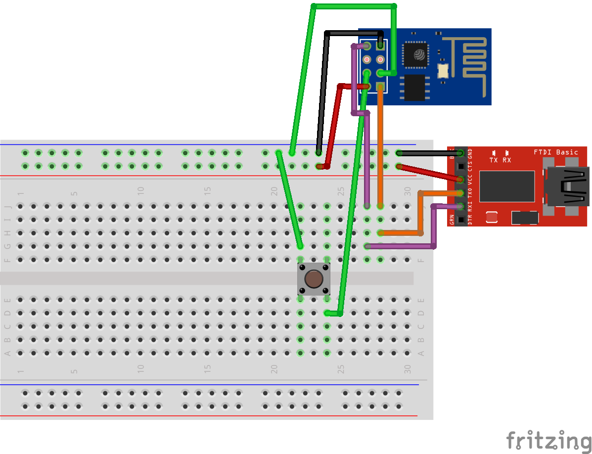
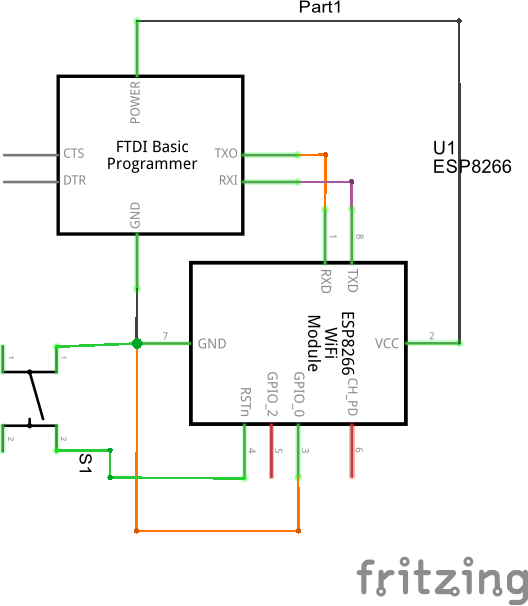
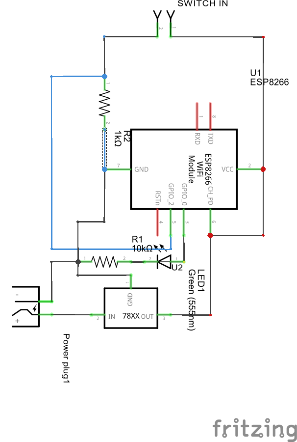
Programming the ESP-01There are many guides that illustrate how to add the Eesp8266 board to the list of boards and Arduino There are also many guides on how to wire up the ESP-01 for programming. For convenience I have included a schematic for how I wired the ESP-01 for programming.
My sketch makes use of another feature of the esp8266 which is SPIFFS, it is essentially small amount of flash memory that files can be written to and read from from inside the sketch. It is used to store the device's configuration as it isn't volatile and keeps the values after resets/power loss. It does require an additional plugin for the Arduino IDE which is available here along with instructions on how to install it and use it.
Once this is all up and running it is all that needs to be done is upload the Device sketch and the included data to the ESP-01.
There are few things I would like to note that could potentially make the process easier. First would be to change the default settings, these are located in the "data" folder in the sketch folder. This is what gets uploaded via SPIFFS. They are the files the device needs to host the configuration pages and store the configuration. They can be modified before uploading so that the device will use the values you want the first time around.
After this is done it is on to wiring up the ESP-01 for switch inputs.
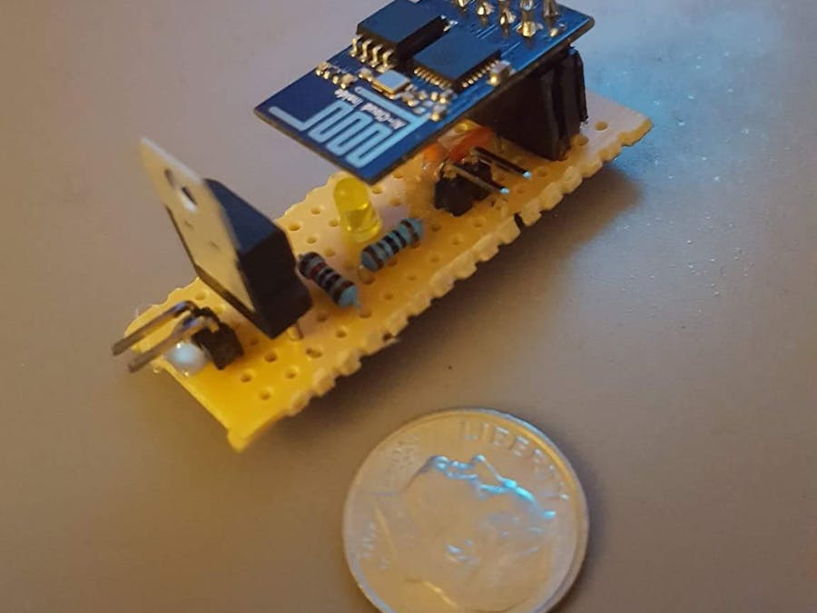
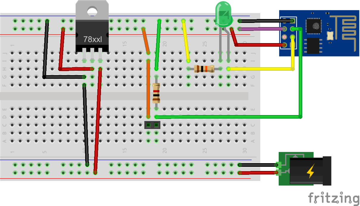
WiringI have again included a diagram of how the ESP-01 should be wired up so that it works with the included sketch. I have also included a wiring diagram in case you want to make a protoboard version like in the thumbnail. The switch port is meant to be able to be used with different kinds of switches. The one stipulation is that it needs to able to be configured to be naturally closed, which is why I used a micro arcade style switch for the trigger. It is also small enough that working it into a small object wouldn't be that much of a challenge.
The other thing worth mentioning is the power input the schematic has a barrel jack only to make it easy to distinguish between the power source and the switch input. In my protoboard mockup seen in the main picture for this project I simply used regular male headers for both the pin input and power, it is really just personal preference. The ESP-01 is also a 3.3v device the power source I was using was a portable battery setup which was around 5v so that is why the voltage regulator is included in the breadboard.
Future Plans- Finish writing the Java device discoverer application
- Fully implement control the other way around so that it doesn't require a complete reprogramming of the board

_3u05Tpwasz.png?auto=compress%2Cformat&w=40&h=40&fit=fillmax&bg=fff&dpr=2)
Comments