

Hardware components | ||||||
 |
| × | 1 | |||
Software apps and online services | ||||||
| ||||||
Some time ago I was working on a robotic system, I found the UART to be a very helpful tool for monitoring the system from a PC, changing between running modes, reading feedback data from sensors for processing the data if the process is slow the device could be controlled from the computer directly.
A more advanced use for this interface is data acquisition, I built a program in Matlab to decode the UART messages with sensor values so they could be ploted vs time.
This data could be used for Model Identification as well.
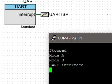
Let's get StartedDrag a UART and interrupt blocks, the UART block I used is SCB UART the block UART would work just like this one (it is just a little more configurable).
So we need to configure the UART communication parameters (these need to be exactly the same on the transmitter and on the receiver side (PSoC and PC). It will work as TX and RX (read and send data).
- BAUD rate (bps): 115200 (comunication speed)
- Data bits: 8bits (each word sent has 8 bits)
- Stop bits: 1 bit
We configure the interrupt source we only want to trigger an interrupt when some data is received on the PSoC so we check RX FIFO not empty.
The interrupt block is set to for an interrupt type as derived. On the code side we need to use the stdlib library, then two function prototypes Init, and the UART interrupt sequence.
We define some UART variables and the newline function for easier referencing, we need a char variable to read from the UART, and a char array to send messages.
#include <stdlib.h>
#include <project.h>
//function prototypes
void Init();
CY_ISR(UARTRX);
//UART variables
#define CR 0x0D
#define LF 0x0A
#define NewLine() UART_UartPutChar(CR); UART_UartPutChar(LF);
char volatile ch;
char msg[7];
int e;
In this example I included a message function that is not fully operational as is the purpose of this function is for feedback of processing data to the PC for this we would need to add sensors that would make the example more complicated, an example of the output message can be in the format (encoder angle, motor speed, time, etc) Ill detail a full example and application later on.
void message(){
NewLine();
UART_UartPutString("variable feedback");//power
/* To output numerical data use itoa to convert numbers to a char array or string
itoa(x*10,msg,10);
UART_UartPutString(msg);*/
}
Now for command interpretation I created a decode function with ch as a parameter depending on its value a function is run, notice each function has a different e value. This will be used later.
void Uartdec(char ch){  //UART DECODING
switch(ch){
	case('1'):{	//Case ch =1
       NewLine();
       UART_UartPutString("Stopped");
       e=1;
		break;}
	case('2'):{    //Case ch =2
		NewLine();
		UART_UartPutString("Mode A");
		e=2;
  		break;}
   case('3'):{    //Case ch =3
       NewLine();
  		UART_UartPutString("Mode B");
       e=3;
		break;}
      //Case ch = different value than above
	/*default:{
		NewLine();
  		UART_UartPutString("Mode");
		e=0;
	}*/
}
}
The main routine will work with the e value, depending on what each mode is supposed to do the program will only run that specific part of the code.
int main()
{
CyGlobalIntEnable;
Init();
	for(;;){
   //Running Mode selection
		switch(e){
	    case(1):{
           //Mode 1
           break;
	   }
        case(2):{
           //Mode 2
           //message(); //this will start sending data message through UART
	        break;
       }
       case(3):{
            //Mode 3
		break;
       }
       case(0):{
		//default Mode
		//NewLine();
           break;
       }
	}
}
}
The init function starts the UART block sends a message and starts the interrupt sequence:
void Init(){
UART_Start();
NewLine();
UART_UartPutString("UART interface");
NewLine();
UARTISR_StartEx(UARTRX);
}
The interrupt sequence reads the value that was received clears the interrupt and enables the Interrupt.
CY_ISR(UARTRX){
UARTISR_Disable();
ch=UART_UartGetChar();
//UART_UartPutChar(ch);
if (0!=ch) Uartdec(ch);  //verify the character that was read by the UART
UART_ClearRxInterruptSource(UART_INTR_RX_NOT_EMPTY);
UARTISR_Enable();
}
The Pioneer kit has to be wired for the UART bridge through the PSoC 5 LP.
Now on the PC install putty. This will be the program used on the computer to read and send data to UART. For the configuration we need to verify in which port is the PSOC connected for this you can right click on the start Menu and run Device Manager here we can find the KitProg and it says it is connected to the COM4 port:
Now we run putty and set up the communication, in the main screen we must change the COM number to COM4 (it has to be the same number as in the device manger), the speed and the connection type Serial. For additional serial parameters you can get into the serial tab.
As soon as the reset button is started the UART interface message is received:
- if we press 1 stop mode is activated
- if we press 2 Mode A is activated
- if we press 3 Mode B is activated
This is an application of the UART interface:


Comments