



Hardware components | ||||||
 |
| × | 1 | |||
Software apps and online services | ||||||
| ||||||
 |
| |||||
Hand tools and fabrication machines | ||||||
 |
| |||||
 |
| |||||
JRFCQAI project transforms a single Arduino UNO-Q board into a full-fledged AI Autonomous Flight Computer + Flight Controller + Web GCS stack for autonomous UAVs. By leveraging the Dual-Brain Architecture, it splits time-critical flight stabilization and high-level Edge AI processing across two dedicated processors on board Arduino UNO-Q.
🚨 The Raw Engineering Approach - No ROS. No Pixhawk or ArduPilot. No QGroundControl or Mission Planner. No MAVLink, DroneKit, or SITL simulators. No off-the-shelf UAV Flight controller hardware or software stacks were used in this project. Every critical layer was engineered completely from scratch to push the absolute limits of the Arduino UNO-Q — achieving fully autonomous, AI-driven flight on a single board.🎬 Flight Demonstration & System Walkthrough
See the JRFCQAI dual-brain platform in action—from hardware walkthrough and ground station setup to closed-loop autonomous flight validation.
👉 Watch JRFCQAI Bench-HIL (Hardware-in-the-Loop) Mode - Props off Safe Testing demonstration video
👉 Watch the Full JRFCQAI Video Playlist
💻 Project GitHub RepositoryThe JRFCQAI project code, hardware schematics, and ongoing development are actively maintained in the GitHub repository below:
👉 GitHub: JRFCQAI Project Repository
🛸 Story & Project PhilosophyWhile most projects utilizing the Arduino UNO-Q explore basic ground robotics, JRFCQAI pushes the platform to its limits: transforming a single UNO-Q board into a full-fledged AI Autonomous Flight Computer + Flight Controller + Web GCS combo for autonomous UAVs.
By leveraging the Dual-Brain Architecture of the UNO-Q, this framework splits time-critical flight stabilization and high-level Edge AI processing across two dedicated processors on a single board.
- STM32U585 Microcontroller (MCU): Runs a deterministic 250Hz PID loop (tested up to 500Hz) over Zephyr RTOS for real-time sensor fusion, motor control, and flight stabilization. All stabilization routines complete under 1ms, leaving ample CPU headroom in the loop for custom mission functions.
- Qualcomm® Dragonwing™ MPU: Runs Debian Linux, processing live USB webcam video via YOLO Light Object Detection inside an Arduino App Lab environment. It acts as a local Web Ground Station streaming live telemetry, AI detections, and direct UI controls to any browser on the local Wi-Fi network or over LTE.
- Auto-Level Flight Mode (Tested)
- Altitude Hold Mode (Tested)
- GPS Position Hold Mode (Tested)
- Automatic Takeoff & Landing (Tested)
- Failsafe System (RTH / Slow descent on signal loss - Tested)
- Real-Time YOLO Object Detection AI (Tested)
- Browser-Based Ground Station control & Live Video Feed (Tested)
- Return to Home (RTH) Execution (Tested)
- Autonomous Waypoint Navigation (Tested - fine tuning progress)
- Autonomous task execution based on Edge Impulse AI model outputs (Tested)
- ZTE LTE WiFi moduel onboard installation and access drone GSC via local network/LTE using tailscale (Tested)
- Dedicated PCB design for Arduino UNO Q & VENTUNO Q integration (In Progress)
- SIMCOM A76XX 4G LTE cellular telemetry stream over CDC ECM (In Progress)
- Extension of framework to Hexacopter & Fixed-Wing platforms (In Progress)
- Arduino UNO-Q 4GB (Qty: 1): Primary Dual-Brain Flight Computer & Ground Station Board. Powered via VIN using a 100μF 50V filter capacitor from a 3S 6000mAh LiPo.
- S500 Quadcopter Frame (Qty: 1): Main carbon fiber / plastic airframe chassis.
- BLDC ESCs >30A (Qty: 4): Driven at custom 400Hz Hardware PWM via pins
D3, D5, D6, and D9. - 2212 920kv Brushless Motors with 1045 prop (Qty: 42-CW 2-CCW): Standard quadcopter propulsion motors.
- MPU6050 (Qty: 1): 6-DOF Gyroscope & Accelerometer connected on I2C1 port running at 400kHz.
- MS5611 (Qty: 1): High-precision Barometric Pressure & Altitude Sensor on I2C1 port.
- HMC5883L (Qty: 1): 3-Axis Digital Magnetometer / Compass module on I2C1 port.
- AT24C256 (Qty: 1): 32KB EEPROM module used for non-volatile storage of PID and IMU/Compass calibration data.
- u-blox NEO-M8N GPS (Qty: 1): High-refresh satellite positioning module connected via UART3 (115200 baud). (If HMC5883L integrated with GPS thanextra HMC5883L not required.)
- Flysky FS-iA6B Receiverand FS-I6 Transmitter (Qty: 1): 10-Channel RC Receiver operating via iBus protocol on UART1 (115200 baud).
- USB Web Camera (Qty: 1): Direct vision feed for live network streaming and real-time YOLO Edge AI object detection.
- 5V >500mA Buck Converter (Qty: 1): External voltage regulator powering the USB webcam in USB Host mode. need 3amp if using ZTE WiFi LTE module onboard.
- 3S >6000mAh LiPo Battery (Qty: 1): Main system flight battery.
- Resistor Divider Pair (Qty: 1 Set): 10K / 1K resistor network on Pin
A0for analog battery voltage telemetry. - External RGB Panel LEDs (Qty: 3): High-brightness status indicators for flight state and startup diagnostic blink codes on
D11, D12, and D13. - ZTE WiFi+LTE module (Optional, Qty: 1): Functions as onboard Wi-Fi range extender and LTE link for remote GCS control. Salvaged from this old Wi-Fi LTE Router.
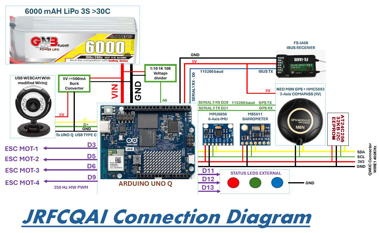
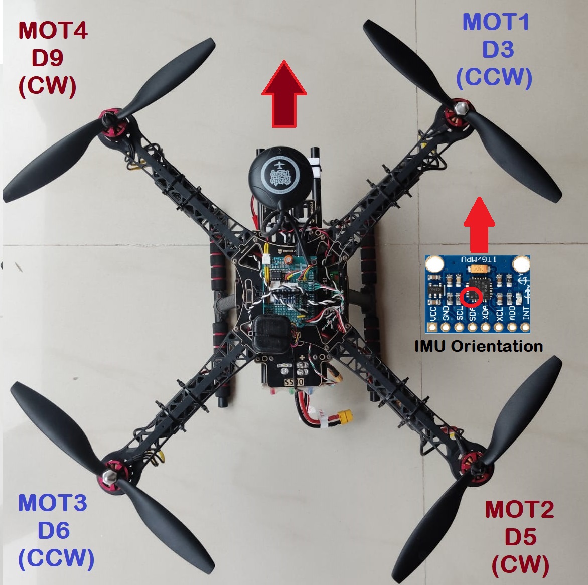
Please refer following images for Hardware connection, Motor Rotation Direction, UNO-Q ESC PIN Mapping and IMU Installation direction.
D2 pin of UNO-Q is used for quick debug loop timing, while pin is high loop execution is carried out and while pin is low there is headroom to execute user tasks. As per attached debug on oscilloscope screenshot in 250Hz loop all critical flight stabilization completes in ~1ms yet giving ~3ms headroom for user tasks. So loop rate can be easily extended up to 500Hz yet having ~1ms for user tasks.
Real-Time Telemetry & System Monitoring :
- 40-Byte Bridge Frame Parsing: Decodes incoming binary telemetry frames (
stm_tx_tel) with XOR checksum validation and header matching (JB). - Live Flight Status: Displays current flight modes (Stabilize, Altitude Hold, GPS Hold, RTH, Waypoints), armed/disarmed state, satellite count, and GPS fix type.
- Flight Metrics & Diagnostics: Tracks relative/max altitude, attitude angles (pitch, roll, yaw), throttle, temperature, and line-of-sight/ground distance.
- Power & Error Tracking: Monitors battery voltage, visual charge level, and flags active system errors (low battery, sensor issues, watchdog timeouts).
Interactive Mapping & Waypoint Navigation :
- GIS Leaflet Map: Features an satellite view map with real-time drone position markers, heading-aligned directional icons, and home coordinates.
- Click-to-Point Planning: Allows dropping route waypoints directly on the map connected by path polylines.
- Automated Waypoint Engine: Executes multi-point routes via a background state machine using packed 12-byte binary command frames (
WP) with handshake retries.
Computer Vision & Autonomous AI Flight :
- Live Video Feed: Embeds an active onboard camera video stream (640x480 resolution) directly into the UI dashboard.
- Object Detection Pipeline: Detects targets, calculates confidence scores, and determines target bounding-box center coordinates.
- Target-Triggered AI Flight: Features an active AI flight toggle that automatically sends altitude commands (
EU.....) when detecting specific targets (such as people). - Live Console Output: Logs detection events and system commands in a 50-entry dark-mode scrolling debug console.
- Configurable FPS and resolution for video stream: In Applab project Default FPS kept 5 FPS to get smooth telemetry over LTE via Tailscale. If you want to just use WiFi telemetry this can be extended up to 30 FPS by changing single line in AppLab python Project.
Manual Control Matrix & REST API :
- 3x4 Command Grid: Dispatches 12 manual 12-byte packed binary commands (
CMD) for Takeoff, Landing, Position Hold, directional movements, and Auxiliary switches (AUX1–3). - FastAPI Backend: Powered by FastAPI/Uvicorn multi-threaded web server exposing JSON endpoints (
/api/data,/api/command,/api/waypoint/*,/api/ai_flight) for live dashboard interaction.
Please refer following screenshot to understand JRFCQAI GCS Web utility usage
To allow safe, rapid iteration without risking hardware during complex autonomous mission tuning, JRFCQAI includes a built-in props-off bench validation mode: Here is Bench HIL demonstration Video.
- Active Hardware Pipeline: Reads live MPU6050/MS5611 IMU telemetry, drives real-time motor PWM outputs at 400Hz via Zephyr RTOS, processes live camera feeds via the Qualcomm® Dragonwing™ MPU, and accepts autonomous navigation commands over Web GCS.
- Closed-Loop Simulation: Emulates spatial displacement feedback (latitude, longitude, altitude) for complex multi-waypoint missions while physical motors respond dynamically on the bench.
- Quick Configuration: Toggle between Bench-HIL mode and full flight mode simply by commenting/uncommenting the HIL mode flag inside
send_telemetry.inoas noted in the source code comments.
Flight Controller Core: Arduino UNO-Q powered directly via VIN using a 100μF 50V filter capacitor from a 3S 6000mAh LiPo.
Sensors (I2C1 QWIIC Port @ 400kHz):
- 1.MPU6050: 6-DOF Gyroscope + Accelerometer
- 2.MS5611: Barometric Pressure / Altitude sensor
- 3. HMC5883L: 3-Axis Magnetometer / Compass
- 4.AT24C256: 32KB I2C EEPROM for storing PID and IMU/Compass/Baro calibration data
GPS & Receiver:
- 1.u-blox NEO-M8N GPS: Connected via UART3 (115200 baud)
- 2. Flysky FS-iA6B Receiver: iBus interface on UART1 (115200 baud)
Actuators & Monitoring:
- 1.4x BLDC ESCs (>30A): Driven at 400Hz on Hardware PWM Pins (
D3,D5,D6,D9) - 2. Frame: S500 Quadcopter frame (tune default PIDs if using alternative frames)
- 3. Battery Telemetry: Voltage monitoring on Pin
A0via a 10K/1K resistor voltage divider - 4. Status Indicators: RGB Status LEDs on
D11,D12,D13
Vision System: Direct USB Webcam connected to the UNO-Q Type-C port, powered externally via a dedicated 5V Buck Converter.
🚨 LED Status & Diagnostic Blink CodesFollowing image represents LED status and diagnostic blink codes for
- Normal Startup LED Procedure (External RGB Panel)
- Onboard GPS Status LED (UNO-Q Onboard Red LED)
- Startup Error Diagnostics (External RGB Panel)
- Runtime Error Diagnostics (External RGB Panel)
Flight Controller Firmware (STM32U5 MCU) & Core Patches :
- 1. Open
UNOQ_JRFCQAI_MAINin the Arduino IDE. - 2. Select your Arduino UNO Q board target.
- 3.Apply Zephyr RTOS Core Patches (Required for 400Hz PWM & GPS Parsing):
Modify Hardware PWM Frequency:Open wiring_analog.cpp located at:C:\Users\xxx\AppData\Local\Arduino15\packages\arduino\hardware\zephyr\0.90.0\cores\arduino\wiring_analog.cppLocate around line 141 and update the implementation to set a custom period:
value = CLAMP(value, 0, maxInput);
//const uint32_t pulse = map64(value, 0, maxInput, 0, arduino_pwm[idx].period);

/*
 * A duty ratio determines by the period value defined in dts
 * and the value arguments. So usually the period value sets as 255.
 */
//(void)pwm_set_pulse_dt(&arduino_pwm[idx], pulse);
const uint32_t custom_period = 2500000UL;
const uint32_t pulse = map64(value, 0, maxInput, 0, custom_period);
(void)pwm_set(arduino_pwm[idx].dev, arduino_pwm[idx].channel, custom_period, pulse, arduino_pwm[idx].flags);
Expand UART Receive Buffer Size:Open ZephyrSerial.h located at:C:\Users\xxx\AppData\Local\Arduino15\packages\arduino\hardware\zephyr\0.90.0\cores\arduino\ZephyrSerial.hLocate line 54 inside ZephyrSerialBuffer and set the buffer array size to 512 bytes:
class ZephyrSerial : public HardwareSerial {
public:
    template <int SZ> class ZephyrSerialBuffer {
        friend arduino::ZephyrSerial;
        struct ring_buf ringbuf;
        uint8_t buffer[512]; // ---> Hardcode SZ to 512
struct k_sem sem;- 4. Flash the sketch to the board to initialize the STM32U585 real-time flight loop.
Ground Station & AI System (MPU)
- 1. Launch Arduino AppLab.
- 2. Import the
JRFC_QAI_GCSPython project. - 3. Run the application to start the web ground station and AI detection engine.
Hardware Note (Camera Troubleshooting):If your USB webcam does not initialize upon booting the Ground Station you need to enable USB Host mode on UNO Q, open the Arduino UNO-Q Shell in AppLab and execute the following commands to force USB Host Mode:
sudo -i
echo host > /sys/kernel/debug/usb/4e00000.usb/mode
Arduino App lab and Arduino IDE Setup for JRFCQAI Web GCS and Flight controller sketch Video :
💡 Key Engineering Breakthroughs & Technical Solutions- Low-Weight Power Routing: Solved USB Host power limitations on boot without adding heavy USB-C PD hubs by routing webcam power to a 5V 500mA Buck Converter and forcing host mode via scripts.
- Zephyr RTOS Core Patches: Overcame the default 500Hz PWM constraint by modifying the underlying Zephyr RTOS hardware core to support custom 400Hz output for precise ESC synchronization.
- Serial Buffer Expansion: Prevented packet dropping on the default 64-byte UART buffer by patching Zephyr to allocate a 512-byte UART RX buffer for loss-free u-blox GPS parsing.
- Deterministic 250Hz Execution Loop: Implemented
k_yield()andk_sleepus()within the flight loop to guarantee a rigid 4ms execution cycle with ~3ms of idle headroom per iteration for user task. In future this can be extended to Deterministic 500Hz Execution Loop and still keeping ~1ms of idle headroom per iteration for user tasks. - Zero-Blocking RPC Bridge: Replaced standard blocking
bridge.call()methods (which added 5–7ms delays) with asynchronousbridge.provide()andbridge.notify()calls for zero-latency telemetry streaming to the UNO-Q Linux MPU and executing AI Autonomous mission commands received from the UNO-Q Linux MPU. - Architecture Migration: Ported and modernized the YMFC-32 Autonomous framework from legacy bare-metal STM32F103 registers to the STM32U5 running Zephyr RTOS, replacing PPM-SUM with native iBus handling and added Autonomous AI based mission capabilities.
Special thanks to Joop Broking, creator of the YMFC-32 Autonomous Flight Controller. His open-source contributions provided the fundamental mathematical foundation for the flight stabilization algorithms ported into this project.
📢 Safety & Usage DisclaimerThis is an experimental, open-source educational project developed strictly for educational and research purposes. Unmanned Aerial Vehicles (UAVs) can cause severe physical injury or property damage if mishandled. This framework is provided "AS IS", without warranty of any kind. Operate experimental hardware entirely at your own risk, follow all local aviation regulations, and adhere to strict safety protocols during testing.
🏁 Final RemarksDeveloping JRFCQAI has been an intensive exercise in bare-metal engineering and physical AI integration. Rather than relying on off-the-shelf stacks, this project pushes the absolute limits of the Arduino UNO Q by building every critical layer completely from scratch:
- Custom Flight Controller Firmware: A deterministic, real-time PID stabilization loop engineered directly on the STM32U5 core using Zephyr RTOS.
- AI-Enabled Ground Control Station: An edge processing pipeline running on the Qualcomm® Dragonwing™ Linux MPU for real-time video streaming, AI Brick (object detection and other), and direct browser UI control.
- Custom Communication & RPC Linkage: A zero-blocking inter-processor bridge linking MCU flight metrics with MPU high-level logic to enable autonomous AI-guided maneuvers and live telemetry.
Creating a fully custom, dual-brain autonomous flight system without using proven drone frameworks is a massive technical undertaking that demands continuous tuning and deep architectural refinement.
JRFCQAI is a long-term commitment. The open-source GitHub repository will be actively maintained and updated with future roadmap milestones, custom PCB hardware designs, and extended edge-AI capabilities as this project continues to evolve.
Cheers,
Team JRFCQAI
Ravi & Madhuri





Comments