


Hardware components | ||||||
| × | 1 | ||||
 |
| × | 1 | |||
 |
| × | 1 | |||
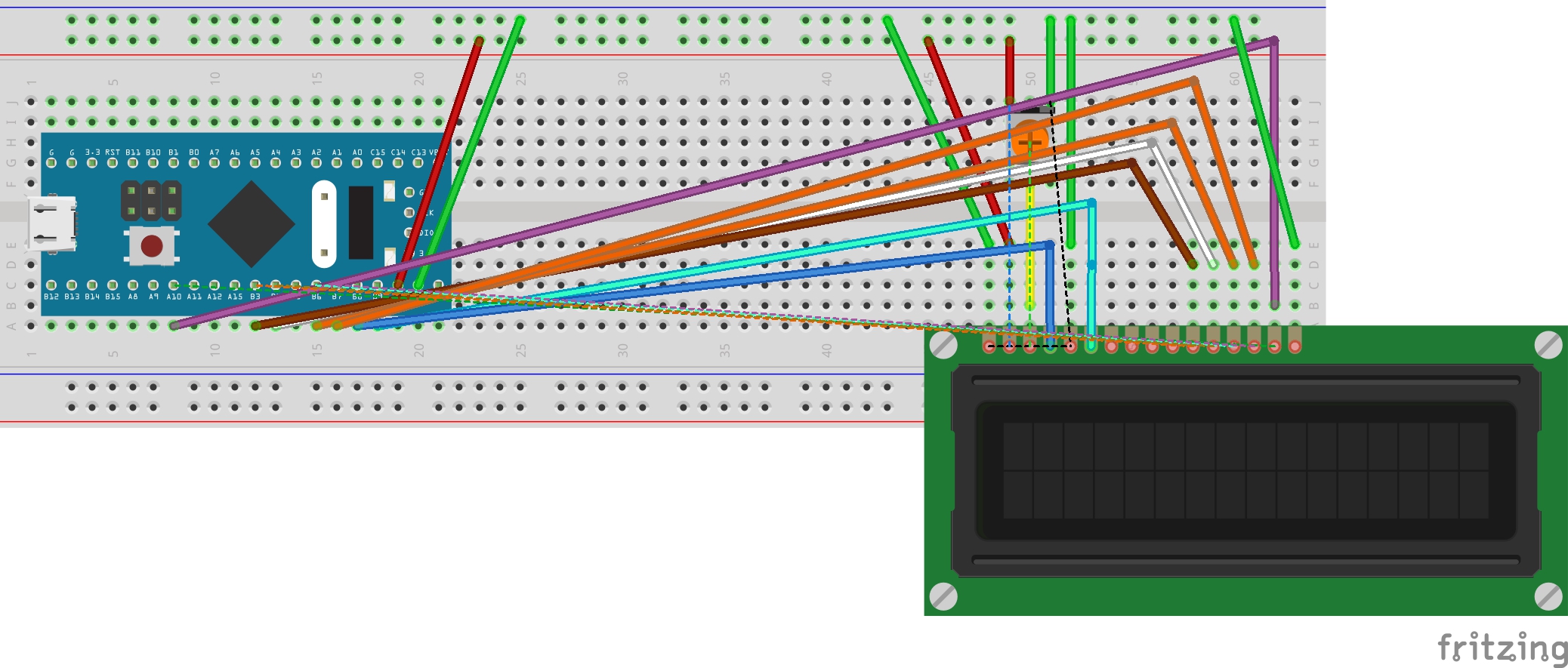
When I saw and built Techmirtz;s "Using 16x2 LCD with Arduino, I started looking at the STM32F103C "Blue Pill" that I had. So I decided to try this. I altered his code to match my board and used a pwm pin for the backlight instead of a resister to VCC. It is a very easy setup on the LCD:
Pin 1 to gnd
Pin 2 to +5V
Pin 3 to wiper of pot that is connected to +5v on one end, and gnd on the other.
Pin 4 RS to PB8
Pin 5 RW to gnd
Pin 6 En to PB9
Pin 7, 8, 9, 10 DB 0-3 Not used
Pin 11 DB 4 to PB3
Pin 12 DB 5 to PB4
Pin 13 DB 6 to PB6
Pin 14 DB 7 to PB7
Pin 15 LED + to PA10 - Backlight
Pin 16 LED - to gnd

Comments