A teacher of technology asked to me to design something easy to build than could be fun.
He agreed that it must be some printed circuit boards made by the student body, but materials should not be more expensive than 20 Euros in total. He said, "you can not be considered an electronic expert if you can not make your own printed circuit boards".
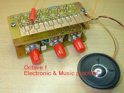
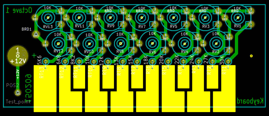
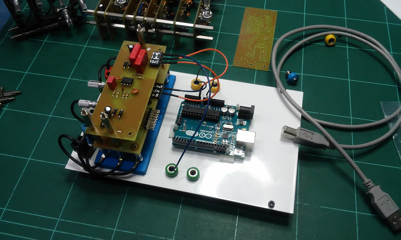
Thought it was a good idea to play music as it would be more fun. A little oscillator that might be considered a synthesizer. It must be modular, so that the students could work with single parts of the project.
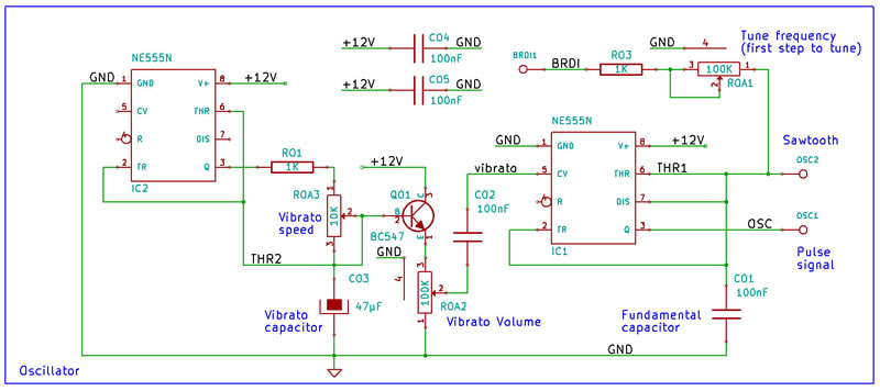
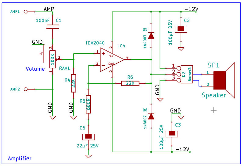
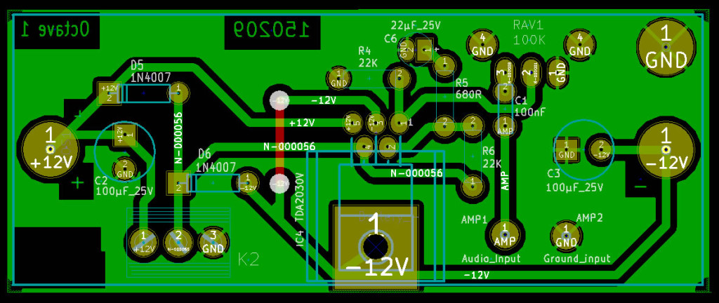
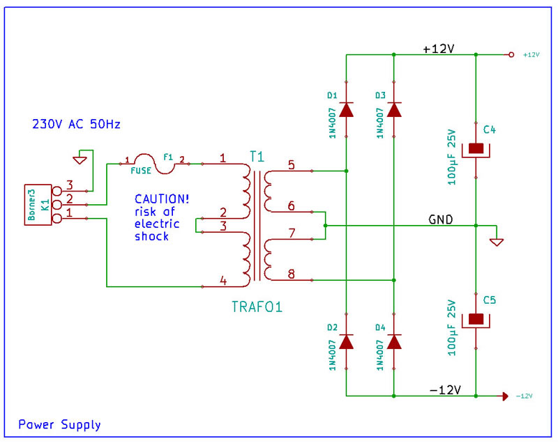
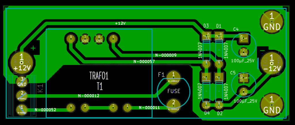
Octave 1 is a system of four circuits:Finally the result was so economic than teacher decided to build the completed instrument by the pupil. There were two versions, first one with a 9V battery, and the second was a 12V symmetrical power supply comparable to professional analogue modular systems. Here only the second version is presented.
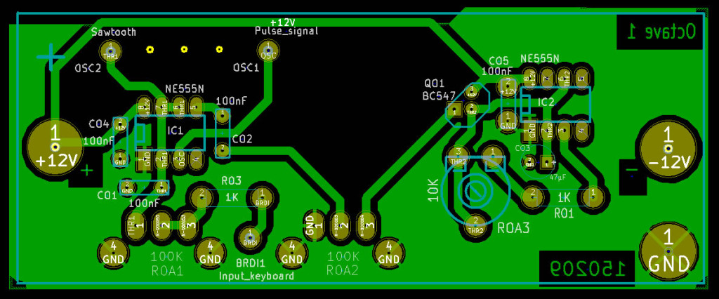
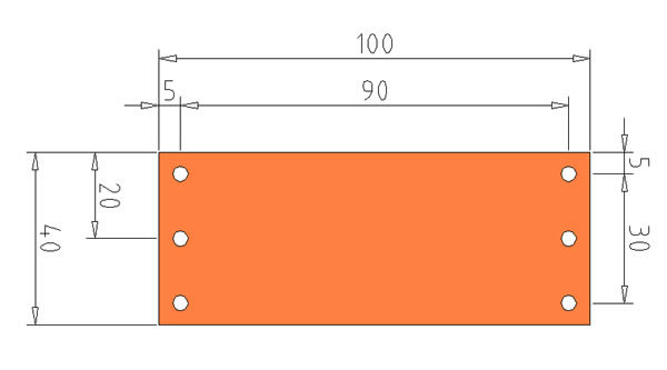
I invite you to make your own Printed Circuit Board (PCB).
A good way is reading this guide:Also you need the original transferable document to print in a laser printer. Use this only if you have totally and exactly components of list. On the contrary test and modify your footprint figures in PCB editor. KiCAD you will make this without change footprint library.
You might use it, and modify for free.
Downloads:AdviceOne year from design was enough for the TDA2030 and TDA2040 to become obsolete. It is more expensive but it is possible to find. It's because that is preparing a new version of the amplifier with LM741 that might load the speaker 0.5W 8 ohm proposed in the project, but it needs something more to make noise.
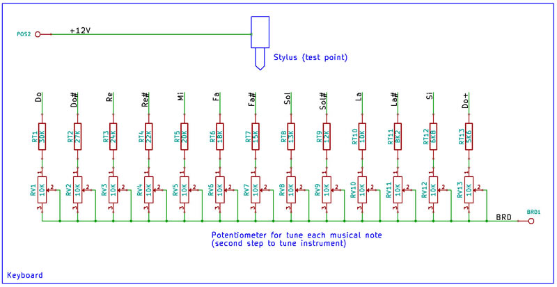
Also about shaft rotary potentiometers, continually changing by intermediate distributors and stock splits. Also recommend changing the PCB layout when have completed material, and print your own transfer document.


Comments