


Hardware components | ||||||
 |
| × | 1 | |||
 |
| × | 1 | |||
 |
| × | 3 | |||
 |
| × | 1 | |||
 |
| × | 1 | |||
 |
| × | 1 | |||
 |
| × | 1 | |||
 |
| × | 1 | |||
Hand tools and fabrication machines | ||||||
 |
| |||||
 |
| |||||
 |
| |||||
 |
| |||||
When we play games that involve dice, one or more of the dice inevitably end up on the floor after an over enthusiastic player tries to roll double 6's. This dice skull solves the problem and, with an added Arduino Nano, lights up red whenever it detects a dice throw. I would have liked for it to make a "roar!" sound but the Nano isn't really up to playing audio.
The skull was 3D printed from a model provided by Windham Graves. See ThingIVerse.com for the file needed to 3D print the skull. Be aware it takes 26 hours to print on a Creality 3 S1 printer using standard quality settings with PLA filament.
The back of the skull is hollow making it easier to install electronics back there.
Optional - After printing, coat the skull in Epoxy using a foam brush that can be tossed out afterwards. After the epoxy dries, spray paint the skull matte black using Rust-oleum Ultra Matte paint and primer.
Find or purchase an on/off switch. Use a Dremel tool to carve out the opening for the on/off switch near the skull's right ear. Don't place the switch in the hole yet, some wires need to be added first (more on this below).
Drill through the switch opening into the "throat" of the skull to make an opening for the RGB LED that lights up the eyes. Use a drill bit about the same diameter as the LED. The switch is placed on the skull's right ear to make the relatively inaccessible right side of the throat accessible for drilling. The sloped angle of the throat makes it easier to drill from the left side so there's no need to make a hole ion the outer skull on that side.
Drill another hole on the other side of the throat for the photo-resistor. The dice will be detected when they interrupt the light going to the photo-resistor from the LED. The detection logic is fairly sensitive to light level changes, so just waving your hand around the eye holes may be enough to set them off. The closer the photo-resistor is to being directly across from the LED, the better the circuit will be at detecting dice.
The 9V battery holder is also 3D printed. See ThingIVerse.com for the print file. The "compact" version of the print file was used but there's plenty of room for either version in the skull.
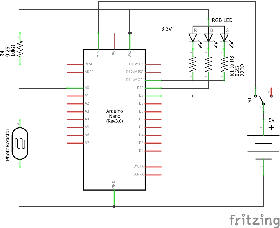
Step 2 : Building the CircuitA small PCB is used to hold the Nano and a two-terminal connector for the battery/switch leads.
Step 2.1 : Solder together Nano, LED, Photo-resistor and associated resistors
The Nano, photo-resistor, regular resistors and LED can be soldered together before the battery and switch are placed in the skull. Use a small two conductor screw down terminal post on the PCB to connect to the Vin and GND terminals of the Nano. This terminal posts will come in handy during final assembly.
Step 2.2: Solder together the switch and 9V battery connector
The switch and battery holder can be soldered together along with a 2 inch (5 cm) wire. Do not screw the battery/switch leads to the PCB.
Step 3 : Programming the NanoUsing the Arduino IDE, upload the following code to the Nano.
// Light up skull code for Arduino Nano
// (C) Copyright 2021 John Dillenburg
// john _at_ dillenburg.org
//
double avgWhenOn;
double avgWhenOff;
long last = 0;
int lightOnLevel = 4;
long lastTrigger = 0;
long triggerCooldown = 500; // milliseconds
int detectThreshold = 10;
long recalibrateInterval = 300000; // milliseconds
long lastRecalibrate = 0;
void setup() {
 Serial.begin(115200);
 pinMode(9, OUTPUT);
 pinMode(10, OUTPUT);
 pinMode(11, OUTPUT);
 pinMode(A0, INPUT);
 calibrate();
 if (Serial) {
   Serial.print("lightOnLevel = ");
   Serial.print(lightOnLevel);
   Serial.print("   avgWhenOn = ");
   Serial.print(avgWhenOn);
   Serial.print("   avgWhenOff = ");
   Serial.println(avgWhenOff);
 }
 detectMode();
}
void calibrate() {
 lightOnLevel = 20;
 avgWhenOn = average(500, lightOnLevel);
 avgWhenOff = average(500, 0);
 while (avgWhenOff - avgWhenOn < detectThreshold && lightOnLevel < 255) {
   lightOnLevel += 16;
   avgWhenOn = average(500, lightOnLevel);
 }
 if (lightOnLevel > 255) lightOnLevel = 255;
 lastRecalibrate = millis();
}
void rgb(int r, int g, int b) {
 analogWrite(9, 255 - r);
 analogWrite(10, 255 - g);
 analogWrite(11, 255 - b);
}
void movementDetected() {
 rgb(255, 0, 0);
 delay(3000);
}
void detectMode() {
 rgb(lightOnLevel, lightOnLevel, lightOnLevel);
}
double average(int duration, int level) {
 rgb(level, level, level);
 long start = millis();
 long count = 0;
 double sum = 0.0;
 while (millis() < start + duration) {
   sum += analogRead(A0);
   count++;
 }
 return sum / count;
}
void loop() {
 int detector = analogRead(A0);
 avgWhenOn = avgWhenOn * 0.999 + detector * 0.001;
 if (Serial && millis() > last + 1000) {
   Serial.print("detector = ");
   Serial.print(detector);
   Serial.print("  avg = ");
   Serial.println(avgWhenOn);
   last = millis();
 }
 if (detector > avgWhenOn + detectThreshold && millis() > lastTrigger + triggerCooldown) {
   if (Serial) {
     Serial.print("triggered ");
     Serial.println(detector);
   }
   movementDetected();
   lastTrigger = millis();
   detectMode();
 }
 if (millis() > lastRecalibrate + recalibrateInterval) {
   calibrate();
 }
}
The code keeps track of the ambient + LED light level using the avgWhenOn variable. If a shadow passes in front of the photo-resistor connected to pin A0, then the value read from A0 will increase and this will trigger the movementDetected() function. The movementDetected() function turns the LED red for 3 seconds.
The avgWhenOn variable uses an infinite impulse response system to average together the latest photo-resistor reading with the old readings. I selected 0.999 and 0.001 as the weights. This may seem to only lightly weight the latest reading, but the Nano loop() function is called so often that the variable settles down to an average value within a second.
The Serial print statements are optional and were coded in such a way that, after installation, they will be skipped.
Step 4 : Putting it TogetherWorking in the back/bottom of the skull, the photo-resistor is placed in the hole drilled in the throat's left side and is glued in place using a generous glob of hot melt glue.
Likewise for the LED on the throat's right side.
Feed the wires for the switch and the 9V battery connector through the switch hole. Screw the two leads down on to the small Nano PCB.
Place the 9V battery into the battery holder and hot melt glue that underneath.
The PCB itself can be crammed into the bottom and will stay in place amongst the tangle of wires.
After turning the skull on, it will flash white on and off as it measures the initial light level. Afterwards, even the slightest shadow passing in front of the eyes will cause the skull to switch on the LED to bright red.
Enjoy!


Comments