

Hardware components | ||||||
| × | 1 | ||||
| × | 1 | ||||
| × | 1 | ||||
| × | 1 | ||||
Software apps and online services | ||||||
| ||||||
| ||||||
 |
| |||||
Hand tools and fabrication machines | ||||||
 |
| |||||
Use promo code ckirk17 at checkout for a 10% discount on all items in cart.
BLE Temperature Controlled OutletItems Needed:
- Outlet
- 14 gauge wire (green, white, black preferred)
About 15 - 20 inches of length for black, and about 10 inches of white and green
- Relay board
- Extension cable (14 or lower gauge)
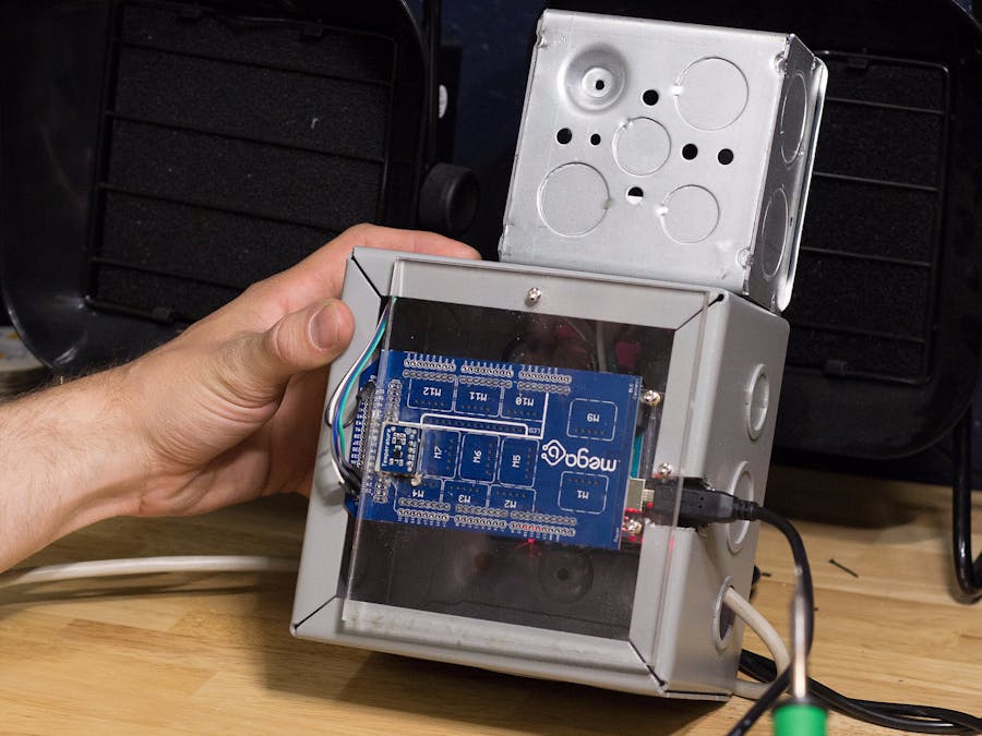
- Box to mount relay board and Bread Mega in
- Some basic wires for the Bread Mega
STEPS:
HARDWARE - How to Build the Outlet Box
- Start by cutting the black 14 gauge wire into 3 small segments (about 2-4 inches). These wires will be used to bridge the power coming in from the wall
- Then cut the black 14 gauge wire into 4 larger segments (about 6-8 inches). These wires will be used to connect individually to each outlet plug and allow us to program the 4 outlets individually. I highly recommend labelling the wires going to the outlets 1-4 so you know which wire goes to which outlet without too much headache.
(Upclose shot of how the wiring should look)
- Notice that for this relay board, each relay has a group of 3 gates, the rightmost gate is what will connect to the outlets.
- Note that wires labeled 1-4 are inserted into those gates. The smaller wires that bridge the power coming in from the wall use the leftmost and middle gates to bridge across.
- Note that it is ok for the smaller wires that are bridging the power to be touching; but absolutely make sure the outlet wires are not being touched by any other wires. Electrical tape is recommended!
- Cut the female end of the extension cord off, and strip off the 3 wires inside. I recommend attaching a little extra length to the stripped wires, however, you can also just strip the wire further down.
This photo is just to show where the power is coming in from the wall.
- Notice that the black wire from the extension cable goes in the middle gate of the 4th relay to the right (labeled 4). From here, the power is bridged (or daisy chained) to each of the other relays. The remaining 4 black wires and the white and green wire from the extension cable will go directly to the outlets.
- Insert the extension cable wire through a hole in your electrical box.
- Place the relay board inside the electrical box and connect the black wire to the middle gate on the 4th relay to the right.
- Direct all remaining wires (4 outlet wires, 1 white wire, and 1 green wire) through a hole at the top of your electrical box.
- Mount your outlet box onto the electrical box and allow the wires to come through.
- Attach the white and green wires to the outlet as shown in the picture. Note the green screen for the green wire. If you are looking at the outlet, the white wire connects on the left.
- Break the tab on the outlet to separate the power distribution between the two outlets.
- Attach the black wires (1 and 3) to the top and bottom of the outlet.
- Repeat the last step with a new outlet, this time use wires 2 and 4.
- Cut a small white wire about 4-5 inches to bridge neutral.
- Repeat this step with a green wire as well to bridge ground.
- Put the cover on the outlet box with the outlets inside
- Label your outlets for convenience
- To set up the Mega-B Bread™Board, place a Breadware temperature sensor in position M8.
- Solder 6 basic Arduino wires to the Mega-B.
- Use two wires to solder into ground and 5v power.
- Solder the other 4 wires into ports 22-25.
- Plug in the 6 wires into the relay board. Your relay board may differ from my pinout, so be sure to read which pins you are plugging into!
- For my project, I cut a piece of acrylic to mount the Mega-B into the electrical box. (I also cut a small hole to let the temperature sensor pick up air from the back of the box.
- Note that this step is not necessary to get your project functioning.
- Mount the acrylic piece to the back of the outlet box, or find a suitable place to mount the Mega-B inside.
- Finally, make sure that you are able to access the USB port on the Mega-B so that you can upload new programs or adjust existing ones.
SOFTWARE - How to Program Breadware
- Click New Project on the left hand side
- Then select Blank Template
- Select Mega-B Bread™Board
- Locate the temp sensor on the right indicated by the red arrow and drag it into position M8.
- Give your temperature sensor a name
- Now it’s time to write the program, first click on Write Firmware.
- Then click on Add If/Then Rule
- At the first drop down menu, select your temperature sensor.
- Then adjust the second line to say “less” than “19” degrees celsius or whichever temperature your preference might be.
- Then click Submit
- Then click AddCode
- Next you need to create the outlets as Global Variables so that the program can access the pins you soldered the wires into.
- Click on Globals
- Next, type in the above code to create names for the pins on the Mega-B Board so that you can control the relay board.
- Then click on Setup
- Type in the above code to initialize the pins you declared in Global.
- Setting the output to “HIGH” will turn all the relays off.
- It is worth noting that this code here only runs one time whereas our code in the Loop section will run over and over.
- Now go back to Loop.
- Now we are going to include code to turn on outlet1 (which switches the relay board connected to outlet1) .
- Use the digitalWrite function to control when we want a relay on or off.
- Now lets add an option to turn our heater off when the temperature gets too hot.
- Select your temperature sensor and this time make sure the second line says “greater or equal than” then enter your desired temperature.
- Finally click the submit button
- Now click the Add Code button
- Now we are going to copy and paste the above highlighted code into the new “if statement”.
- Now adjust the code so that the new digitalWrite function is set to “HIGH” to turn off the relay.
- Now let’s design our mobile app!
- Click on Design App.
- Now add some text into your app by clicking on the Add Button next to App Text
- Give your text box a name and then click create.
- Now lets add a way to stream the data to our mobile app.
- Click on Interactive.
- Click on Add Data Display and give your data display box a name.
- Then click create.
- Now let’s create a light indicator that will tell you if your outlet is on or not.
- Click on App Indicator Light and give the light a name.
- Then click create.
- Go back to the General tab and create another App Text box, this time describing what the indicator light is for.
- Then click Create.
Your app should look something like this by the time your are done editing.
- Now let’s go back to Write Firmware so we can include the data streaming and light indicator.
- Click on Write Firmware.
- Now let’s add the code for data streaming.
- First click on Add If/Then Rule, then for the output, select the Data Display you created in the App Design tab.
- Then click Submit.
- Then click Add Code
- Now we are going to delete the surrounding “If Statement” since we want this code to run all the time.
- Your code should look like this now.
- Now let’s create the indicator light code.
- First click on Add If/Then Rule, then select the indicator light as the output.
- Then select Turn “On” and pick any color you’d like.
- Then click submit.
- Now click Add Code.
- Since you already have an “If Statement” that says when to turn on the heater, we are going to stick the highlighted piece of code into the above if statement.
- Then delete the empty “If Statement”.
- Your code should look like this after you have moved the code.
- Now lets repeat our steps to turn the light off when the outlet turns off.
- First click on Add If/Then Rules
- Now click on the indicator light for the output, and select Turn “Off”.
- Then click submit.
- Then click Add Code.
- Now take the highlighted piece of code and insert into the second “If Statement” where you declare when to turn the outlet off.
- Your code should like this at the end.
- Congratulations! You are now ready to download your program and upload it to your board.
- Once connected to your Mega-B, you should see your app appear that you designed earlier under "Available Devices"
John Kirkpatrick
Posted by  Anela deLaveaga
Anela deLaveagaThanks to John Kirkpatrick.


Comments