

Hardware components | ||||||
| × | 1 | ||||
 |
| × | 1 | |||
 |
| × | 1 | |||
 |
| × | 1 | |||
Software apps and online services | ||||||
 |
| |||||
Hand tools and fabrication machines | ||||||
 |
| |||||
You may be familiar with the ATtiny series of microprocessors from Microchip such as the ATtiny85 or ATtiny2313. These chips powered small systems like the Digispark series. Unfortunately, they had limited Flash (usually no more than 8K) and even more limited RAM (usually less than 1K).
Now a new series of ATtiny chips are available with more memory and functionality. They even compete with the more expensive and larger ATmega range of chips. The ATtiny1614 that I will be looking at has 16K Flash Memory and 2K RAM in a 14-pin SOIC package.
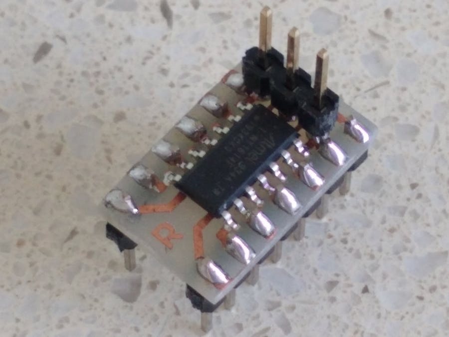
Using a breadboardOne of the problems with experimenting with these new chips are that they only come as Surface Mount Devices (SMD). This makes it hard to use on a breadboard. I have made a simple adapter board that allows a ATtiny1614 chip to be used as standard Dual-In-Line (DIL) device.
The Eagle files have been included should you wish to get the adapter board commercially made or you can make it yourself. I made mine using the Toner method. Note: The DIL pin layout differs from the SMD pin layout. I did this on purpose so I could use a single sided PCB and keep the 0.3in width. The 0.3in width was important so that the adapter can plug into a standard 14pin IC socket. The UPDI/RESET, VCC and GND pins have there own separate header so that a programmer can be connected to the board even when the adapter has been soldered into another PCB.
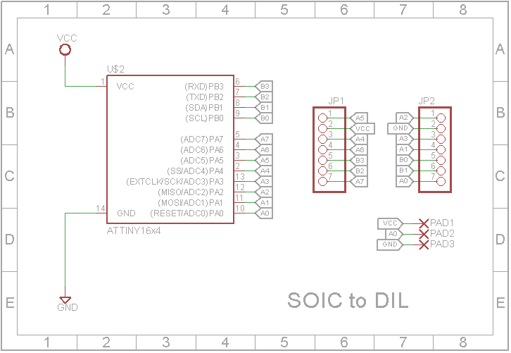
One of the biggest changes in these processors is the way they are programmed. They use a system called Unified Program and Debug Interface (UPDI for short). This interface uses the RESET pin to program and/or debug the device. In this tutorial I will be using a Arduino Nano to send the correct signals to UPDI/RESET pin. Once the processor is programmed, the Arduino Nano is no longer required.
1. Unzip the attached "SpenceKonde - jtag2updi.zip" file into your Arduino program folder and program the Arduino Nano. Note: It's OK that the jtag2updi.ino file is empty as the actual code resides in the other files.
2. To stop the Arduino Sketch being over-written when you program the ATtiny, you need to disable the RESET line on the Arduino. You do this by adding a 10uF capacitor between RESET and GND. A short reset pulse will only reset the ATtiny and not the Arduino. You can still RESET the Arduino by holding down the RESET button for a longer time.
3. Connect a 4K7 resistor between D6 on the Arduino and the RESET/UPDI pin on the ATtiny as shown in the schematic above. Also add the +5V and GND connections from the Arduino Nano to power the ATtiny.
Step 2: Installing the megaTinyCore in the Arduino IDEThis board package can be installed via the board manager. The boards manager URL is:
http://drazzy.com/package_drazzy.com_index.json
- File -> Preferences, enter the above URL in "Additional Boards Manager URLs"
- Tools -> Boards -> Boards Manager...
- Select "megaTinyCore by Spence Konde" and click "Install".
Once the board has been installed in the IDE, select it from the Tools menu.
Make sure you select the Chip that you are about to program. Also libraries such as the Adafruit Neopixel Library won't work on a 20 MHz clock so you may need to wind the clock speed back to 16 MHz or 8 MHz if you are running the chip from a 3V3 supply.
The Programmer needs to be set to jtag2updi (megaTinyCore).
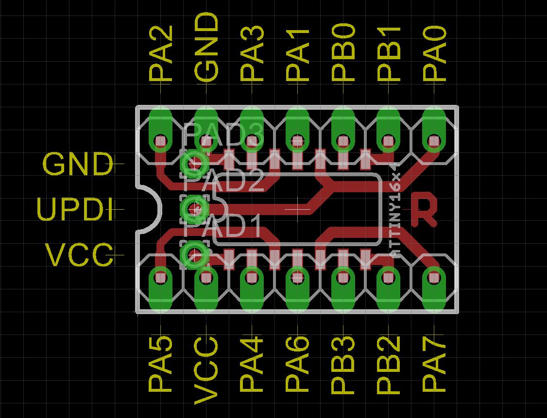
Pin mapping and the Arduino IDETo access the physical IO pins in the Arduino IDE using digitalRead, digitalWrite, analogRead or analogWrite, use the pin map above to determine the pin number to use. Note: Unlike the ATmega328, the new ATtiny processors don't have separate analog pins. Whether a pin is analog or digital depends on which function you use to access it.
Blink ExampleTo test the programmer, wire a LED and 470 ohm resistor between pin 2 (PA4) of the ATtiny1614 and +5V.
Open the Blink_ATTiny1614.ino file in the Arduino IDE and select "Upload using programmer" from the Sketch menu.
Ignore the error message "avrdude: jtagmkII_initialize(): Cannot locate "flash" and "boot" memories in description".
The LED should start to blink.
/*
Blink
Turns an LED on for one second, then off for one second, repeatedly.

BOARD: ATtiny1614/1604/814/804/414/404/214/204
Chip: ATtiny1614
Clock Speed: 20MHz
Programmer: jtag2updi (megaTinyCore)
*/

#define LED_BUILTIN 0 //PA4 (Pin 2)

// the setup function runs once when you press reset or power the board
void setup()
{
    // initialize digital pin LED_BUILTIN as an output.
    pinMode(LED_BUILTIN, OUTPUT);
}

// the loop function runs over and over again forever
void loop()
{
    digitalWrite(LED_BUILTIN, HIGH);   // turn the LED on (HIGH is the voltage level)
    delay(1000);                       // wait for a second
    digitalWrite(LED_BUILTIN, LOW);    // turn the LED off by making the voltage LOW
    delay(1000);                       // wait for a second
}
Note: Physical pin 2 (PA4) is D0 in the Arduino IDE
Color changer exampleIn this example, I will use the Adafruit Neopixel library to control a WS2812B led via a potentiometer. (I used a 10K potentiometer but any value from 1K to 100K will work in this case).
#include <Adafruit_NeoPixel.h>
#ifdef __AVR__
#include <avr/power.h>
#endif

/*---------------------------------------------------------
BOARD: ATtiny1614/1604/814/804/414/404/214/204
Chip: ATtiny1614
Clock Speed: 16MHz
Programmer: jtag2updi (megaTinyCore)
----------------------------------------------------------*/

#define LED 2	//(PA6)
#define PIXELS 1
#define POT 0	//(PA4)

// Parameter 1 = number of pixels in strip
// Parameter 2 = Arduino pin number (most are valid)
// Parameter 3 = pixel type flags, add together as needed:
//   NEO_KHZ800  800 KHz bitstream (most NeoPixel products w/WS2812 LEDs)
//   NEO_KHZ400  400 KHz (classic 'v1' (not v2) FLORA pixels, WS2811 drivers)
//   NEO_GRB     Pixels are wired for GRB bitstream (most NeoPixel products)
//   NEO_RGB     Pixels are wired for RGB bitstream (v1 FLORA pixels, not v2)
//   NEO_RGBW    Pixels are wired for RGBW bitstream (NeoPixel RGBW products)
Adafruit_NeoPixel strip = Adafruit_NeoPixel(PIXELS, LED, NEO_GRB + NEO_KHZ800);

// IMPORTANT: To reduce NeoPixel burnout risk, add 1000 uF capacitor across
// pixel power leads, add 300 - 500 Ohm resistor on first pixel's data input
// and minimize distance between Arduino and first pixel.  Avoid connecting
// on a live circuit...if you must, connect GND first.
void setup()
{
    //Serial.begin(115200);
    pinMode(POT, INPUT);
    pinMode(LED, OUTPUT);
    strip.begin();
    strip.setBrightness(255);
    strip.show(); // Initialize all pixels to 'off'
}

void loop()
{
    uint8_t angle = map(analogRead(POT), 0, 1023, 0, 255);
    uint32_t color = Wheel(angle);
    //Serial.println("Angle: " + String(angle) + ", Color: " + String(color));
    colorWipe(color, 5);
}

// Fill the dots one after the other with a color
void colorWipe(uint32_t c, uint8_t wait)
{
    for(uint16_t i=0; i<strip.numPixels(); i++)
    {
        strip.setPixelColor(i, c);
        strip.show();
        delay(wait);
    }
}

// Input a value 0 to 255 to get a color value.
// The colours are a transition r - g - b - back to r.
uint32_t Wheel(byte WheelPos)
{
    WheelPos = 255 - WheelPos;
    if(WheelPos < 85)
    {
        return strip.Color(255 - WheelPos * 3, 0, WheelPos * 3);
    }
    if(WheelPos < 170)
    {
        WheelPos -= 85;
        return strip.Color(0, WheelPos * 3, 255 - WheelPos * 3);
    }
    WheelPos -= 170;
    return strip.Color(WheelPos * 3, 255 - WheelPos * 3, 0);
}With the extra Flash and Static RAM incorporated in these new ATtiny processors, not to mention the new internal component features, it opens new doors for even smaller projects. I think you will find that it will be worth-while reading the datasheets for these new processors. It could be the start of your next exciting project.
UpdateSee Create Your Own UPDI Programmer for details on creating a permanent UPDI programmer .


Comments