

Hardware components | ||||||
| × | 1 | ||||
| × | 1 | ||||
| × | 1 | ||||
 |
| × | 1 | |||
 |
| × | 1 | |||
| × | 1 | ||||
| × | 1 | ||||
Software apps and online services | ||||||
 |
| |||||
Hand tools and fabrication machines | ||||||
 |
| |||||
 |
| |||||
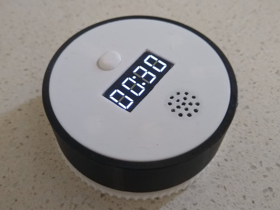
Recently I built an Attiny85 Twist-to-Set Kitchen Timer by bobson.h. After finishing the build, I found that the optical rotary encoder had a number of problems which I won't go into here.
Instead I decided to start over and redesign the mechanism to use a mechanical rotary encoder.
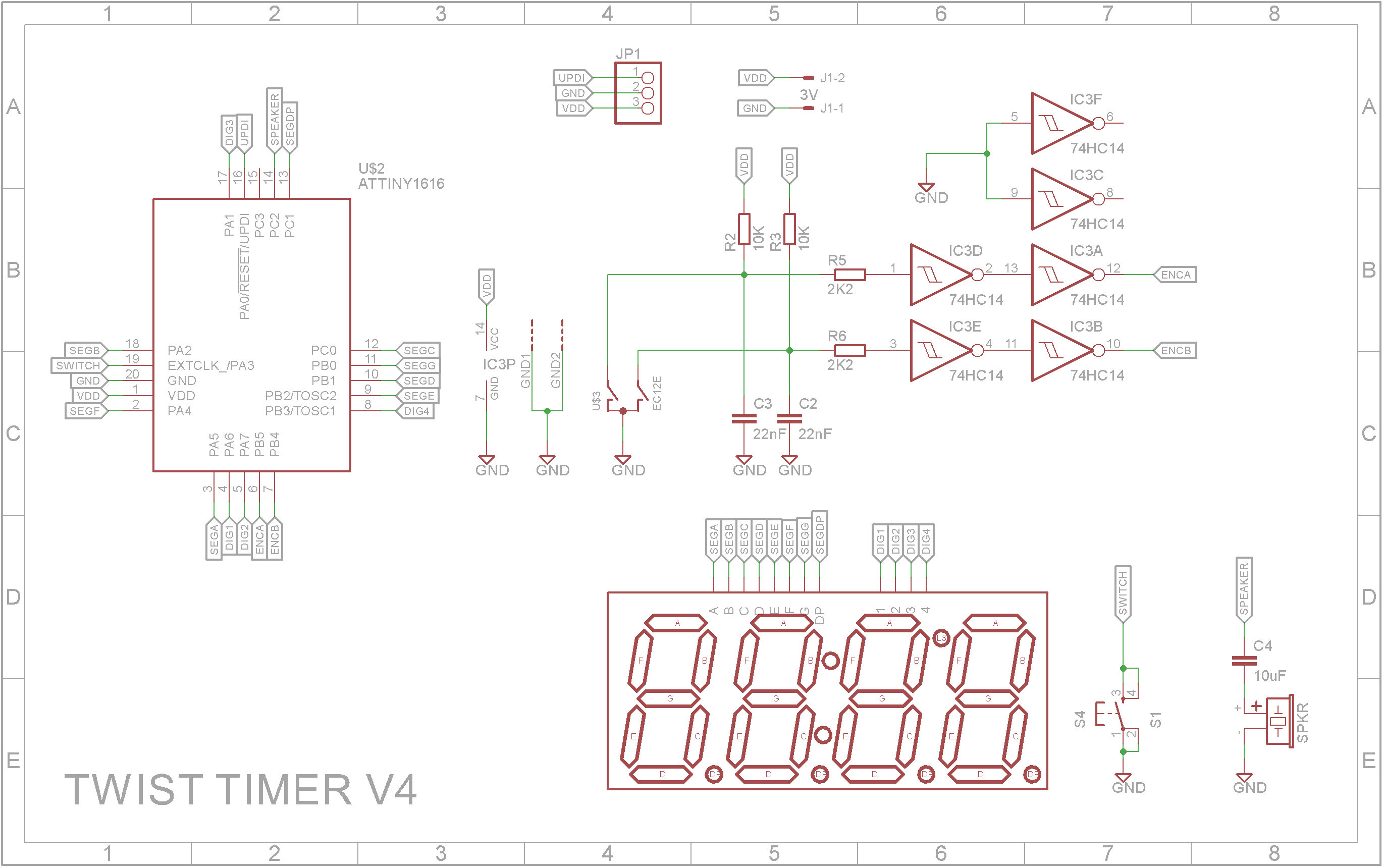
The circuit is designed around a ATtiny3216 microprocessor. This 20pin device has enough IO pins for the 4-Digit 7-Segment clock display, the rotary encoder output, a push button switch and speaker. It also uses very little power in sleep mode. The rotary encoder contacts are debounced using an RC network and Schmitt trigger (74HC14).
The STL files are included. Either take these to a 3D print shop or if you have your own printer, run them through your slicing software. I used a 0.1mm layer height for "Twist - Button.stl" and 0.2mm layer height for the rest of the pieces.
"Twist - Bottom.stl" and "Twist - Ring.stl" require supports touching the build plate only.
"Twist - Rim.stl" should be printing using a contrasting color.
For "Twist - Top.stl", drill out the two PCB mounting holes with a 2.5mm drill and create a thread with a 3mm tap.
Glue "Twist - Ring.stl" to one end of "Twist - Rim.stl" using super glue. Make sure you orientate "Twist - Rim.stl" correctly. Test it on "Twist - Bottom.stl" first, it will only turn correctly if orientated correctly on the base. The Rim is glued to the open side.
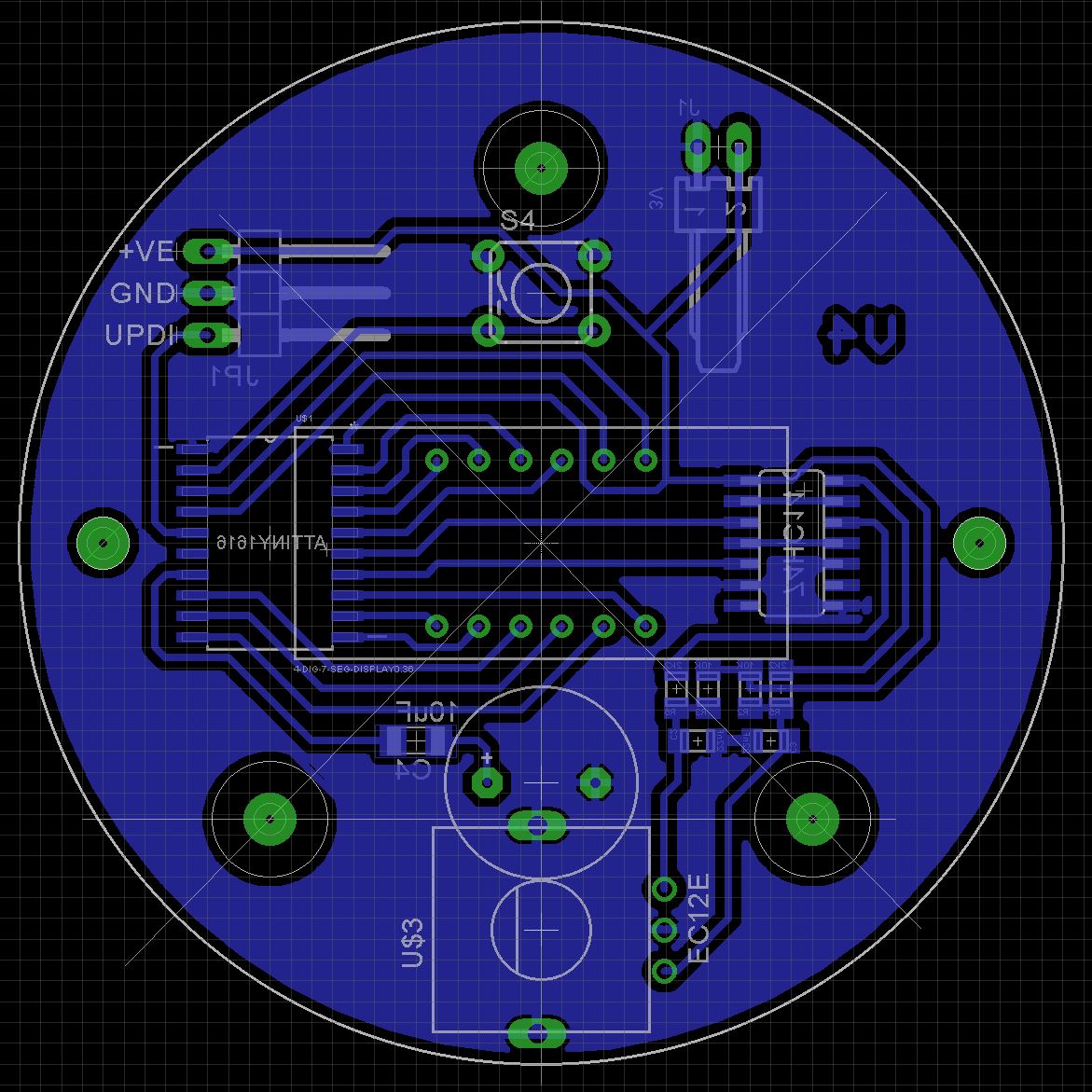
The PCBAs the ATtiny3216 microprocessor only comes as a Surface Mount Device (SMD), I decided to use SMD packages for most of the components in the build.
The Eagle files have been included should you wish to have the board commercially made or you can do as I did and make it yourself. I used the Toner method.
Assembly - Step 1Start by adding the SMD components. I find it easier to use solder paste rather than use solder from a reel when soldering SMD components.
Also solder the pin header for the UPDI programmer and the polarized connecter for the battery connection onto the copper side of the board.
Add switch and display to the top-side of the board.
Add the rotary encoder to the bottom side of the board. (I found that I had to chop off the left over spindle after the pinion gear was added to the rotary encoder. You may want to do this now).
Add the buzzer to the top side of the board. Make sure that the rotary encoder lug doesn't short out the underside of the buzzer.
Place the button top in the top section and carefully push the assembled board in place. Screw it down with two 6mm M3 screws.
Take your glued Rim and Ring assembly and slide it over the top. You may have to file down the teeth of "Twist - Pinion.stl" so as to ensure that lateral force is minimized. Too much lateral force will stop the rotary encoder from operating correctly.
Add a double AAA battery contact set to "Twist - Bottom.stl" and wire up as shown below. When inserting the contacts into the slots, don't force them in place. Instead heat the metal with a hot iron (careful not to touch the plastic) and when the metal is hot enough, it slides down with very little force. Be patient and don't press hard with your soldering iron as you might end up breaking the soldering iron's Bakelite bits. (I did once!)
The ATtiny3216 is part of the new breed of ATtiny microprocessors. Unlike the earlier series such as the ATtiny85, the new breed use the RESET pin to program the CPU. To program it you need a UPDI programmer. I made one using a Arduino Nano. You can find complete build instructions at Create Your Own UPDI Programmer. It also contains the instructions for adding the megaTinyCore boards to your IDE.
The 3-pin header is designed to be connected to the UPDI programmer.
Once the board has been installed in the IDE, select it from the Tools menu.
Select Board, chip, clock speed and the COM port that the Arduino Nano is connected to.
The Programmer needs to be set to jtag2updi (megaTinyCore).
Open the sketch and upload it to the ATtiny3216.
Final assemblyNow you can screw on the bottom and add the batteries.


Comments