

Hardware components | ||||||
| × | 1 | ||||
 |
| × | 1 | |||
| × | 1 | ||||
| × | 1 | ||||
 |
| × | 1 | |||
 |
| × | 1 | |||
Software apps and online services | ||||||
 |
| |||||
Hand tools and fabrication machines | ||||||
 |
| |||||
 |
| |||||
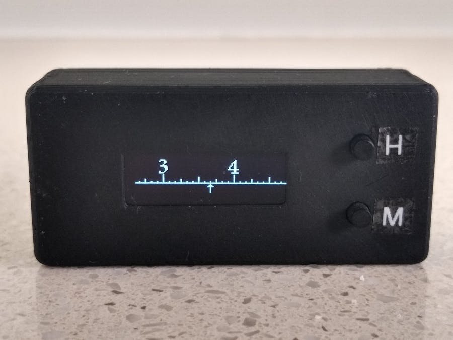
On the Technoblogy website, David Johnson-Davies designed a Timescale Clock based on a ATtiny84 microprocessor. This seemed like a great project to upgrade with a PCB and a 3D printed case. I also changed the circuit to use a more modern microprocessor.
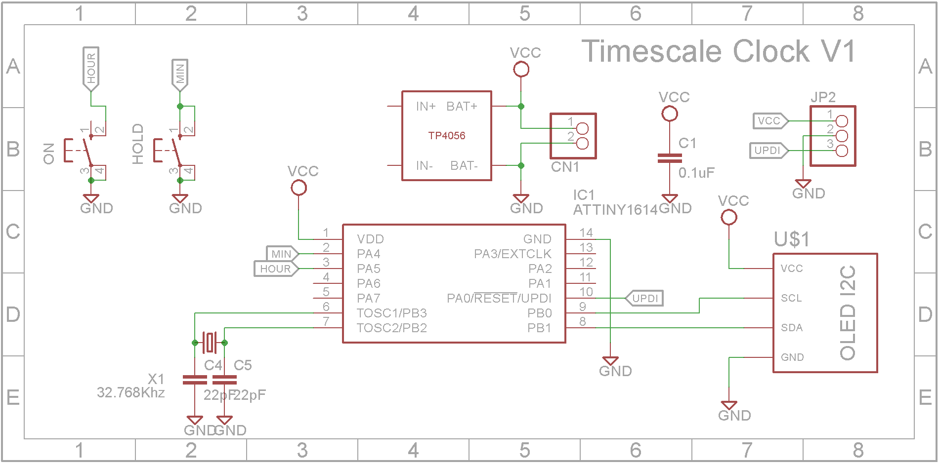
VideoSchematicThe updated circuit is based around the ATtiny1614 microprocessor. It has 16K Flash memory and 2K RAM. The ATtiny1614 has a built in Real Time Clock. The RTC can use its internal 32.768kHz clock or a 32.768kHz external crystal. The external crystal providing a higher degree of accuracy and stability.
As the clock is designed to run from a 3.7V 120mA Li-Ion battery, the circuit includes a TP4056 Li-Ion battery charging unit.
3D printingThe STL files are included. Either take these to a 3D print shop or if you have your own printer, run them through your slicing software. I used a 0.2mm layer height and no supports.
If the lid is loose, add blue painters tape around the rim of the bottom until the fit is tight.
The PCBAs the ATtiny614 microprocessor only comes as a Surface Mount Device (SMD), I decided to use SMD packages for the capacitors as well.
The Eagle files have been included should you wish to have the board commercially made or you can do as I did and make it yourself. I used the Toner method.
Assembly - Step 1Start by adding the SMD components. I find it easier to use solder paste rather than use solder from a reel when soldering SMD components.
Also solder the pin header for the UPDI programmer and the polarized connecter for the battery connection onto the copper side of the board. Also add 4 single pin headers to mount the TP4056 module. Don't add this module yet until the switches have been soldered in place.
Solder the 32.768kHz watch crystal to the copper side of the board. Use some double-sided tape to secure it and also isolate the crystal case from shorting out any of the copper tracks beneath it.
Add the two tactile switches (9mm shaft).
Glue some packing near the buttons for the display to sit on. I used a old pin header with the pins removed as it will match the height of the pin header on the OLED display.
Add the OLED display.
Finally solder on the TP4056 module to the 4 single header pins on the copper side of the board.
Screw the board into the case using four 4mm M2 screws.
Plug in the battery.
Unlike the earlier ATtiny series such as the ATtiny85, the ATtiny1614 uses the RESET pin to program the CPU. To program it you need a UPDI programmer. I made one using a Arduino Nano. You can find complete build instructions at Create Your Own UPDI Programmer. It also contains the instructions for adding the megaTinyCore boards to your IDE.
All the components are 5V tolerant so provided the battery is not present, you can power it from the UPDI programmer. If the battery is installed, just connect the GND and UPDI wires and leave off the VCC wire.
Thanks David Johnson-Davies for a another great project. It makes for an interesting time piece.


Comments