/*-------------------------------------------------------------------------
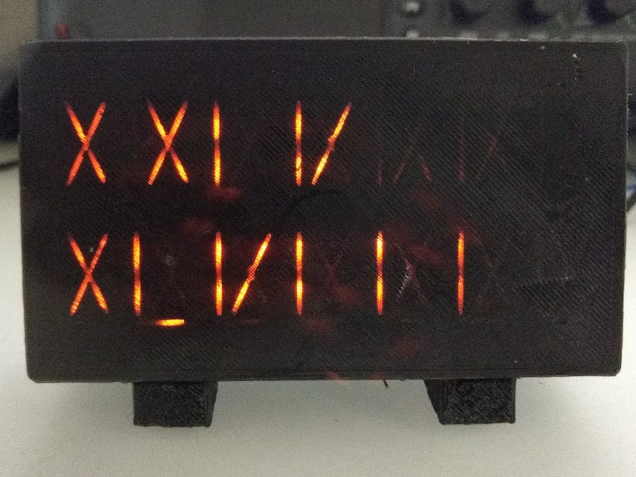
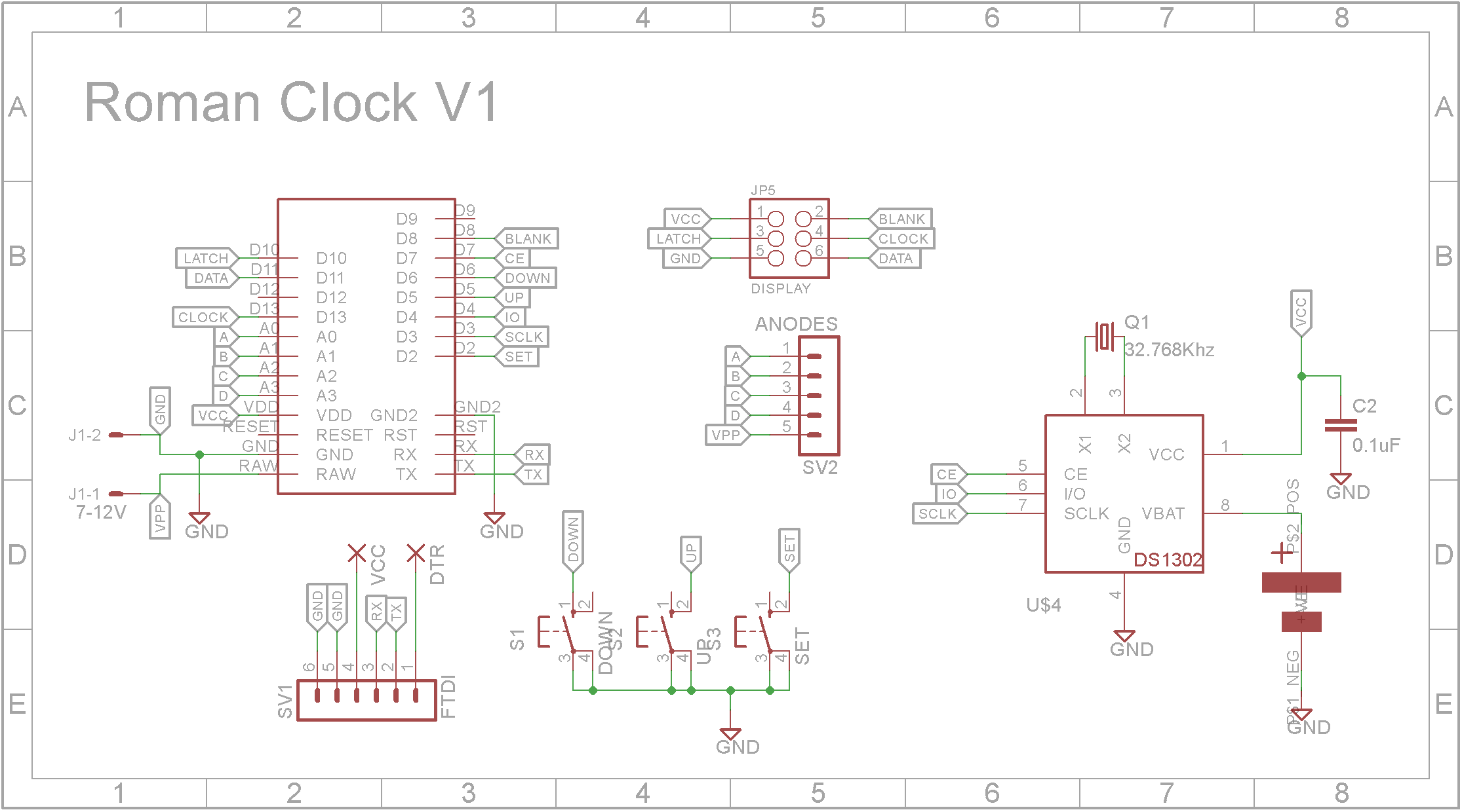
The Roman Numerial Clock
Concept: Radarmus (https://www.thingiverse.com/thing:4771222)
2021-03-02 V1 John Bradnam (jbrad2089@gmail.com)
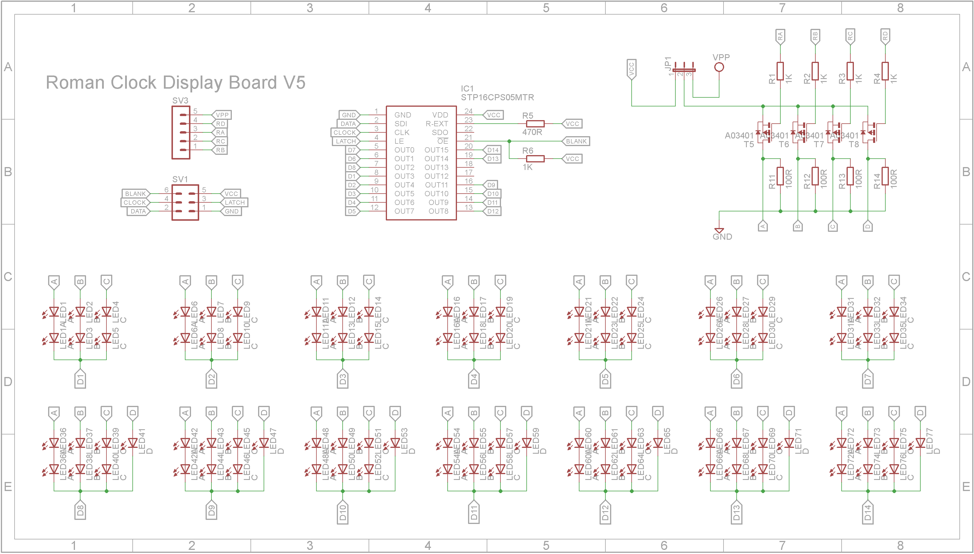
- LEDs are an array of 4 columns | \ / _ (anodes) x 14 digits (cathodes)
Cathodes are connected to a STP16CPS05 16 Channel shift register with constant current outputs
Anodes are connected to 4 P-Channel MOSFETs (Active LOW)
- Created code base
*/
//#define DEBUG
#include <SPI.h>// SPI Library used to clock data out to the shift registers
#include <TimeLib.h>
#include <DS1302RTC.h>
#define DATA_PIN 11 // used by SPI, must be pin 11
#define CLOCK_PIN 13 // used by SPI, must be 13
#define BLANK_PIN 8 // same, can use any pin except 12 you want for this, just make sure you pull up via a 1k to 5V
#define BLANK_PORT PORTB //Port for BLANK pin
#define BLANK_BIT 0 //Pin number of BLANK pin
#define LATCH_PIN 10 //can use any pin except 12 you want to latch the shift registers
#define LATCH_PORT PORTB //Port for LATCH pin
#define LATCH_BIT 2 //Pin number of LATCH pin
#define ANODE_A A0 // A anode
#define ANODE_B A1 // B anode
#define ANODE_C A2 // C anode
#define ANODE_D A3 // D anode
#define RTC_CE 7 // RTC CE pin
#define RTC_IO 4 // RTC IO pin
#define RTC_CLK 3 // RTC SCLK pin
#define SW_SET 2 // SET switch input
#define SW_UP 5 // UP switch input
#define SW_DOWN 6 // DOWN switch input
#define ROWS 4 // Number of rows of LEDs
#define LEDS_PER_ROW 16 // Number of leds on each row
#define BYTES_PER_ROW 2 // Number of bytes required to hold one bit per LED in each row
//Bit buffer for matrix
byte ledStates[ROWS][BYTES_PER_ROW]; //Store state of each LED (either off or on)
byte ledNext[ROWS][BYTES_PER_ROW]; //Double buffer for fast updates
int activeRow = 0; //this increments through the anode levels
//The digits are not wired to the corresponding pins on the STP16CPS05
//This is to simplify routing on the PCB. This table maps the logical channels
//to the physical pins.
uint8_t digitMap[] = {0,1,7,6,5,4,3,15,14,8,9,10,11,2,12,13};
//Bit order is abcd, digits are left to right
// | \ /
// a b c
// | \ /
// ----d----
const uint16_t unitsFont[] PROGMEM =
{
0b0000000000000000, //0
0b1000000000000000, //1
0b1000100000000000, //2
0b1000100010000000, //3
0b1000101000000000, //4
0b1010000000000000, //5
0b1010100000000000, //6
0b1010100010000000, //7
0b1010100010001000, //8
0b1000011000000000 //9
};
const uint16_t tensFont[] PROGMEM =
{
0b0000000000000000, //0
0b0110000000000000, //10
0b0110011000000000, //20
0b0110011001100000, //30
0b0110100100000000, //40
0b1001000000000000, //50
0b1001011000000000, //60
0b1001011001100000, //70
0b1001011001100110, //80
0b0110100100000000 //90 (no C)
};
//Secondary menus
enum ClockEnum { CLK, CLK_H, CLK_M };
ClockEnum clockMode = CLK;
//OK I know the DS1302 is a pretty crappy RTC but I have a lot of them to use up :-)
DS1302RTC rtc(RTC_CE, RTC_IO, RTC_CLK);
#define FLASH_TIME 100 //Time in mS to flash digit being set
#define STEP_TIME 350 //Time in mS for auto increment or decrement of time
int lastMinutes = -1; //Used to detect change in minute to update display
int nowH = 0; //Current Hour
int nowM = 0; //Current Minute
int setH = 0; //Hour being set
int setM = 0; //Minute being set
long flashTimeout = 0; //Flash timeout when setting clock or alarm
bool flashOn = false; //Used to flash display when setting clock or alarm
long stepTimeout = 0; //Set time speed for auto increment or decrement of time
//---------------------- General initialisation ----------------------------
void setup()
{
SPI.setBitOrder(MSBFIRST);//Most Significant Bit First
SPI.setDataMode(SPI_MODE0);// Mode 0 Rising edge of data, keep clock low
SPI.setClockDivider(SPI_CLOCK_DIV2);//Run the data in at 16MHz/2 - 8MHz
#ifdef DEBUG
Serial.begin(115200);// if you need it?
#endif
noInterrupts();// kill interrupts until everybody is set up
clearDisplay(); //Clear the primary buffer
refresh(); //Transfer to display buffer
activeRow = 0;
//We use Timer 1 to refresh the display
TCCR1A = B00000000; //Register A all 0's since we're not toggling any pins
TCCR1B = B00001011; //bit 3 set to place in CTC mode, will call an interrupt on a counter match
//bits 0 and 1 are set to divide the clock by 64, so 16MHz/64=250kHz
TIMSK1 = B00000010; //bit 1 set to call the interrupt on an OCR1A match
OCR1A = 150; // you can play with this, but I set it to 150, which means:
// our clock runs at 250kHz, which is 1/250kHz = 4us
// with OCR1A set to 150, this means the interrupt will be called every (150+1)x4us 0.6mS,
// which gives a refresh rate (all 4 anodes) of 417 times per second
//finally set up the Outputs
pinMode(LATCH_PIN, OUTPUT);//Latch
pinMode(DATA_PIN, OUTPUT);//MOSI DATA
pinMode(CLOCK_PIN, OUTPUT);//SPI Clock
//Setup anode pins
pinMode(ANODE_A, OUTPUT);
pinMode(ANODE_B, OUTPUT);
pinMode(ANODE_C, OUTPUT);
pinMode(ANODE_D, OUTPUT);
//Setup switches
pinMode(SW_SET, INPUT_PULLUP);
pinMode(SW_UP, INPUT_PULLUP);
pinMode(SW_DOWN, INPUT_PULLUP);
//Setup RTC pins
//Check if RTC has a valid time/date, if not set it to 00:00:00 01/01/2018.
//This will run only at first time or if the coin battery is low.
//setSyncProvider() causes the Time library to synchronize with the
//external RTC by calling RTC.get() every five minutes by default.
setSyncProvider(rtc.get);
if (timeStatus() != timeSet)
{
#ifdef DEBUG
Serial.println("Setting default time");
#endif
//Set RTC
tmElements_t tm;
tm.Year = CalendarYrToTm(2020);
tm.Month = 06;
tm.Day = 26;
tm.Hour = 7;
tm.Minute = 52;
tm.Second = 0;
time_t t = makeTime(tm);
//use the time_t value to ensure correct weekday is set
if (rtc.set(t) == 0)
{ // Success
setTime(t);
}
else
{
#ifdef DEBUG
Serial.println("RTC set failed!");
#endif
}
}
clearDisplay();
refresh();
delay(100);
//pinMode(BLANK_PIN, OUTPUT);//Output Enable important to do this last, so LEDs do not flash on boot up
SPI.begin();//start up the SPI library
interrupts();//let the show begin, this lets the multiplexing start
delay(500);
clockMode = CLK;
}
//--------- TIMER1 interrupt routine to update the display ------------
ISR(TIMER1_COMPA_vect)
{
BLANK_PORT |= 1 << BLANK_BIT; //The first thing we do is turn all of the LEDs OFF, by writing a 1 to the blank pin
//Turn on all columns
for (int shift_out = 0; shift_out < BYTES_PER_ROW; shift_out++)
{
SPI.transfer(ledStates[activeRow][shift_out]);
}
//Enable row that we just outputed the column data for
digitalWrite(ANODE_A, (activeRow == 0) ? LOW : HIGH);
digitalWrite(ANODE_B, (activeRow == 1) ? LOW : HIGH);
digitalWrite(ANODE_C, (activeRow == 2) ? LOW : HIGH);
digitalWrite(ANODE_D, (activeRow == 3) ? LOW : HIGH);
LATCH_PORT |= 1 << LATCH_BIT;//Latch pin HIGH
LATCH_PORT &= ~(1 << LATCH_BIT);//Latch pin LOW
BLANK_PORT &= ~(1 << BLANK_BIT);//Blank pin LOW to turn on the LEDs with the new data
activeRow = (activeRow + 1) % ROWS; //increment the active row
pinMode(BLANK_PIN, OUTPUT);
}
//---------------------- Main program loop ----------------------------
void loop()
{
if (clockMode == CLK)
{
//DateTime now = rtc.now();
time_t t = now();
nowH = hour(t);
nowM = minute(t);
if (nowM != lastMinutes)
{
lastMinutes = nowM;
showTime(nowH, nowM);
#ifdef DEBUG
Serial.println("Current time: " + String(nowH) + ":" + String(nowM));
#endif
}
}
readBtns(); //Read buttons
}
//--------------------------------------------------
//Read buttons state
// Handles setting of time
void readBtns()
{
if (digitalRead(SW_SET) == LOW)
{
delay(10);
if (digitalRead(SW_SET) == LOW)
{
clockMode = (clockMode == CLK_M) ? CLK : (ClockEnum)((int)clockMode + 1);
switch (clockMode)
{
case CLK_H:
setH = nowH;
setM = nowM;
flashTimeout = millis() + FLASH_TIME;
flashOn = false;
break;
case CLK_M:
flashTimeout = millis() + FLASH_TIME;
flashOn = false;
break;
case CLK:
#ifdef DEBUG
Serial.println("Set time: " + String(setH) + ":" + String(setM));
#endif
//Set RTC
tmElements_t tm;
tm.Year = CalendarYrToTm(2020);
tm.Month = 1;
tm.Day = 1;
tm.Hour = setH;
tm.Minute = setM;
tm.Second = 0;
time_t t = makeTime(tm);
//use the time_t value to ensure correct weekday is set
if (rtc.set(t) == 0)
{ // Success
setTime(t);
}
else
{
#ifdef DEBUG
Serial.println("RTC set failed!");
#endif
}
//force update
lastMinutes = -1;
break;
}
//Wait until button is released
while (digitalRead(SW_SET) == LOW)
{
delay(10);
}
showTime(setH, setM);
}
}
if (clockMode != CLK)
{
if (millis() > flashTimeout)
{
flashTimeout = millis() + FLASH_TIME;
flashOn = !flashOn;
showTime(setH, setM, (clockMode == CLK_H && flashOn), (clockMode == CLK_M && flashOn));
}
if (millis() > stepTimeout)
{
if (digitalRead(SW_UP) == LOW)
{
switch (clockMode)
{
case CLK_H:
setH = (setH + 1) % 24;
break;
case CLK_M:
setM = (setM + 1) % 60;
}
showTime(setH, setM, (clockMode == CLK_H && flashOn), (clockMode == CLK_M && flashOn));
stepTimeout = millis() + STEP_TIME;
}
else if (digitalRead(SW_DOWN) == LOW)
{
switch (clockMode)
{
case CLK_H:
setH = (setH + 23) % 24;
break;
case CLK_M:
setM = (setM + 59) % 60;
}
showTime(setH, setM, (clockMode == CLK_H && flashOn), (clockMode == CLK_M && flashOn));
stepTimeout = millis() + STEP_TIME;
}
}
}
}
//--------------------------------------------------
//show the time
//h = hours (0..11)
//m = minutes (0..59)
void showTime(int h, int m)
{
showTime(h, m, true, true);
}
//show the time
//h = hours (0..23)
//m = minutes (0..59)
//he = hours enable (true/false)
//me = minutes enable (true/false)
void showTime(int h, int m, bool he, bool me)
{
#ifdef HOUR12
if (h >= 12)
{
h = h - 12;
}
if (h == 0)
{
h = 12;
}
#endif
displayRomanNumber((he) ? h : 0, true, false);
displayRomanNumber((me) ? m : 0, false, false);
refresh();
}
//--------------------------------------------------
//Display a number in roman numerals
// number - (0 to 59) - note 0 is blank
// top - true to display top number, false to display bottom number
// centered - true to center number on display
void displayRomanNumber(int number, bool top, bool centered)
{
uint8_t shift;
uint32_t mask;
//Get the bits for the tens portion of the number
uint16_t ft = pgm_read_word_near(&tensFont[min(number / 10, 9)]);
uint16_t fu = pgm_read_word_near(&unitsFont[number % 10]);
uint8_t ct = 0;
mask = 0b1111000000000000;
while (ct < 4 && (ft & mask) != 0)
{
ct++;
mask = mask >> 4;
}
//Count ones
uint8_t cu = 0;
mask = 0b1111000000000000;
while (cu < 4 && (fu & mask) != 0)
{
cu++;
mask = mask >> 4;
}
uint8_t c = ct + cu;
uint8_t r = (top) ? 0 : 7;
uint8_t o = (centered) ? (7 - c) >> 1 : 0; //Calculate offset for centering
for (int i = 0; i < 7; i++)
{
if (i < o)
{
setDigitInArray(0,r + i);
}
else if (i < (o + ct))
{
if (i == o)
{
shift = 12;
}
setDigitInArray((ft >> shift) & 0x0F, r + i);
shift = shift - 4;
}
else if (i < (o + ct + cu))
{
if (i == (o + ct))
{
shift = 12;
}
setDigitInArray((fu >> shift) & 0x0F, r + i);
shift = shift - 4;
}
else
{
setDigitInArray(0,r + i);
}
}
}
//--------------------------------------------------
//Sets the bit in the 6 byte array that corresponds to the physical column and row
// s = 4 bit segment (3 - Seg A, 2 - Seg B, 1, Seg C, 0 - Sed D)
// c = column (0 to 13 - representing 14 digits - top row 0 to 6, bottom row 7 to 13)
void setDigitInArray(uint8_t s, int c)
{
uint8_t cx = digitMap[c];
int by = cx >> 3;
uint8_t bi = cx - (by << 3);
uint8_t mask = 0b00001000;
for (int r = 0; r < ROWS; r++)
{
if (s & mask)
{
ledNext[r][1 - by] |= (1 << bi);
}
else
{
ledNext[r][1 - by] &= ~(1 << bi);
}
mask = mask >> 1;
}
}
//--------------------------------------------------
//Transfers the working buffer to the display buffer
void refresh()
{
memcpy(ledStates, ledNext, ROWS * BYTES_PER_ROW);
}
//--------------------------------------------------
//Clears the working buffer
void clearDisplay()
{
//Clear out ledStates array
for (int r = 0; r < ROWS; r++)
{
for (int c = 0; c < BYTES_PER_ROW; c++)
{
ledNext[r][c] = 0;
}
}
}


_3u05Tpwasz.png?auto=compress%2Cformat&w=40&h=40&fit=fillmax&bg=fff&dpr=2)

Comments