


Hardware components | ||||||
 |
| × | 1 | |||
 |
| × | 1 | |||
| × | 1 | ||||
 |
| × | 1 | |||
| × | 1 | ||||
Hand tools and fabrication machines | ||||||
 |
| |||||
Today microprocessors tend to dominate many of the electronic projects that are built today. They reduce component counts and are becoming even more versatile. Even the new tinyAVR® microprocessors now have programmable user circuits built in. 40 years ago when microprocessors were limited and quite expensive, many projects involved a number of discrete components and basic integrated circuits.
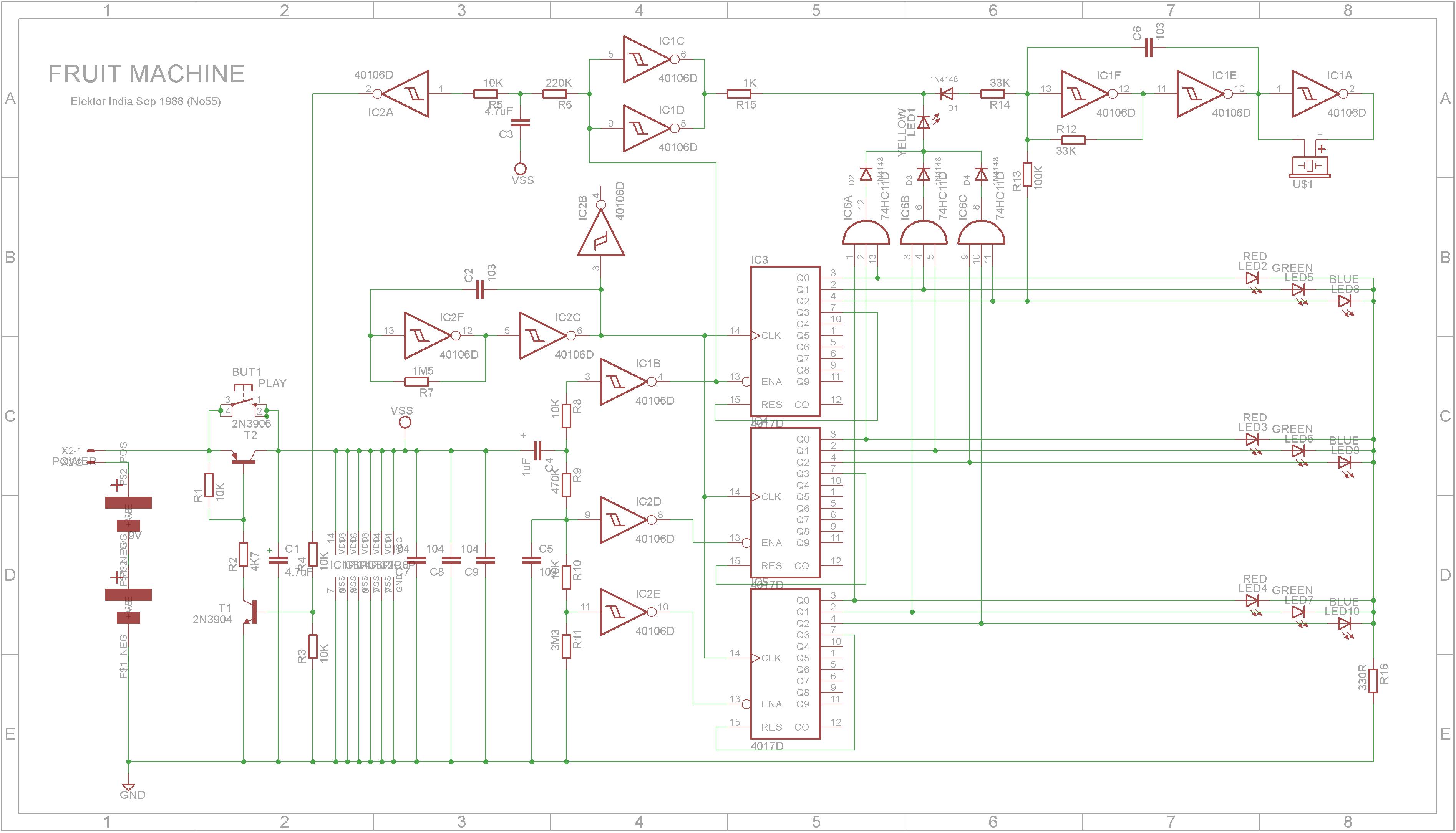
Going back through an archive of old electronic magazines, the following One Arm Bandit circuit looked an interesting build.
At first the circuit might seem quite complicated, but if you break it down into its logical parts, it is actually quite simple.
The oscillator produces a square wave clock whose frequency is determined by R7 and C2.
Three 4017 decade counters are driven from the clock signal. Each decade counter has their Q3 output pin connected to their RESET pin. This means each will continuously count to 3 and start over again. Their output pins drive the LEDs. IC6A, IC6B ad IC6C detect when all the same color LEDs are lit. The diodes D2, D3 and D4 form a 3-Input OR gate and the YELLOW LED will light up when any of the outputs from the AND gates go HIGH.
Each 4017 counter is enabled when its ENABLE pin is LOW.
When power is first applied by pressing the start button, C4 will pass current until it charges up. The outputs from IC1B, IC2D and IC2E will all go LOW starting each 4017 decade counter to start running. At the same time C5 will charge so that when C4 stops charging, it will discharge into the voltage divider network of R11, R10. When C4 stops charging, the output to IC1B will go HIGH stopping wheel one. As C5 discharges, the voltage across it will decrease. At a certain level, the output of IC2E will go HIGH stopping Wheel three and finally the output of IC2D will go HIGH stopping Wheel two.
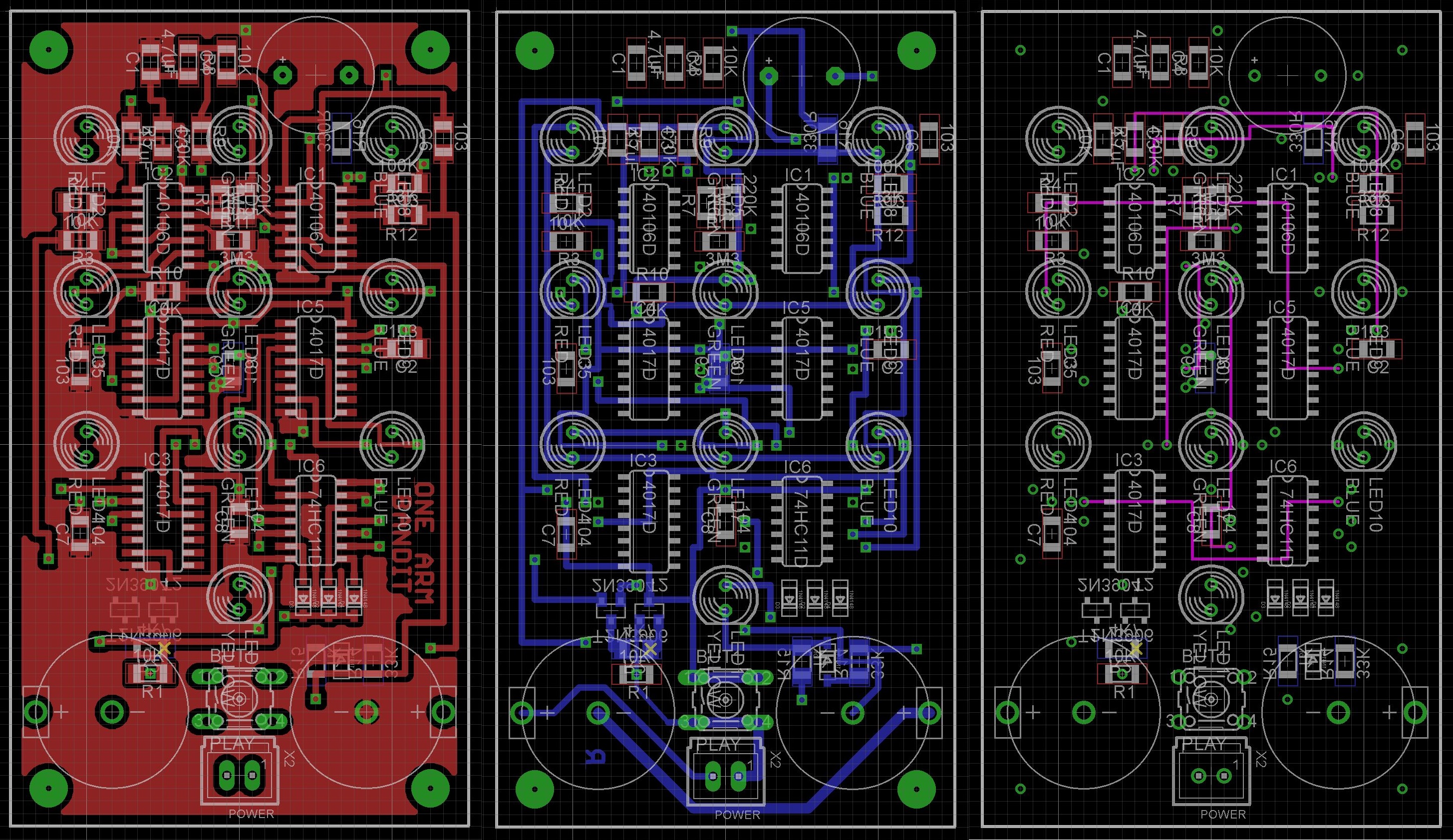
BuildI originally built this using through-hole components exclusively. The Eagle Files have been included should you wish to build this version.
I have a number of cheap 85mmx50mmx20mm cases which I bought a while ago on eBay. They were less than a $1 each. To fit this circuit into the box, a number of SMD (surface mount devices) components are used.
The Eagle files for the PCB have been included should you wish to get them commercially made or you can choose to make them yourself. The board is double-sided so a commercial manufactured board with through-hole plating, a solder-mask and stencil makes the build a lot simpler.
I used the Toner method to make mine and dipped them in tin solution after they were etched.
After I completed the build, I couldn't get it to run using the button cells. Maybe they were no good (they were cheap batteries bought off eBay after all). Rather that go out and buy batteries, I modified the case and board to run from a 9V DC power brick.
Discreet electronics without microprocessors is still fun. It's a pity in some-ways that it is a dying art but if you are interested in looking at old electronic magazines, the best source that I have found is https://worldradiohistory.com/


Comments