

Hardware components | ||||||
 |
| × | 1 | |||
| × | 1 | ||||
| × | 1 | ||||
 |
| × | 1 | |||
| × | 3 | ||||
 |
| × | 1 | |||
Software apps and online services | ||||||
 |
| |||||
Hand tools and fabrication machines | ||||||
 |
| |||||
 |
| |||||
| ||||||
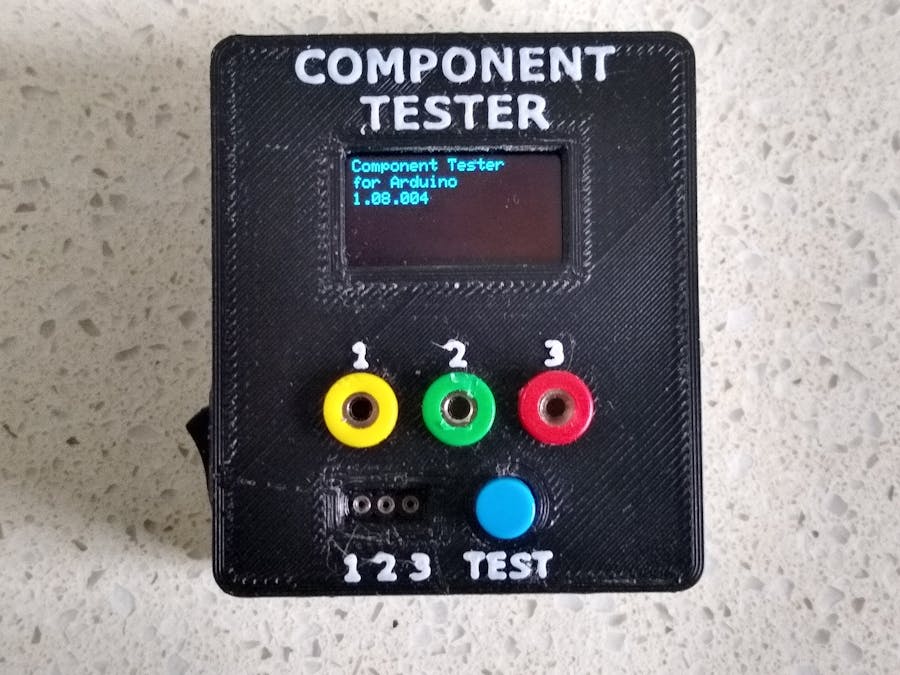
When starting my journey into the world of electronics, I obtained a lot of parts by disassembling discarded electronic devices to salvage the individual components. One of the issues I had was identifying what some of the components were and whether they were any good. Even now, I still find it worthwhile to confirm the identity of the leads on transistors even on brand new ones.
There are many builds of component testers around and this is just one more of them. The software I used identifies most of the standard components; Resistors, Capacitors, Inductors, Diodes (and double diodes), Transistors, J-FETs, MOS-FETs, SCRs or Thyristors, Triacs. It failed to recognize Diacs, UJT's (interpreted as a double-diode) and Zener diodes (interpreted as a normal diode).
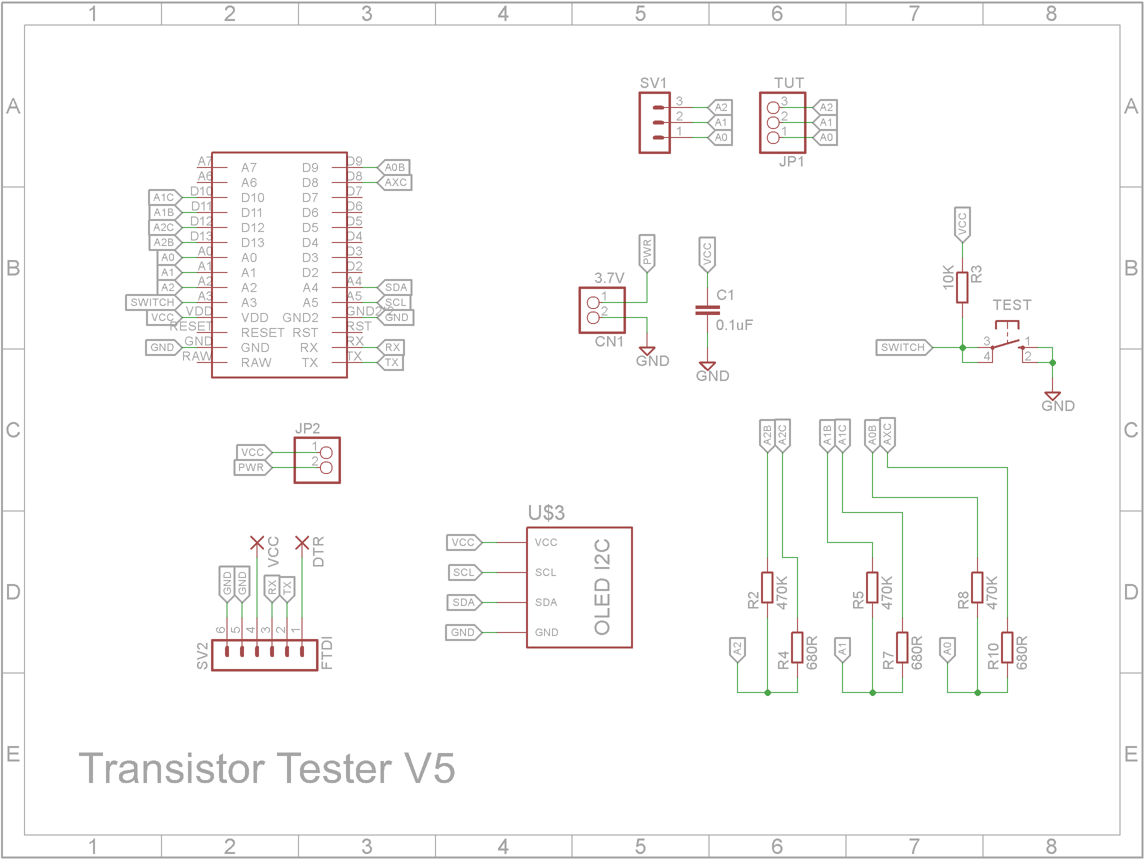
The circuit uses a Arduino Pro Mini and OLED screen.
When obtaining a Arduino Pro Mini, be aware of the different styles they come in.
In the picture above, I designed the PCB for the variant on the far right.
The Arduino Mini Pro is soldered onto the copper side of the board so as to reduce the size of the finished unit.
3D printingPrinting of "Transistor Tester V2 - Case.stl" and "Transistor Tester V2 - Front.stl" are sliced using a 0.2mm layer height without any supports.
To print "Transistor Tester V2 - Text.stl", use a 0.2mm layer and switch to a contrasting filament at the start of layer 4.
Use glue or double sided tape to fix the Front and Text prints together.
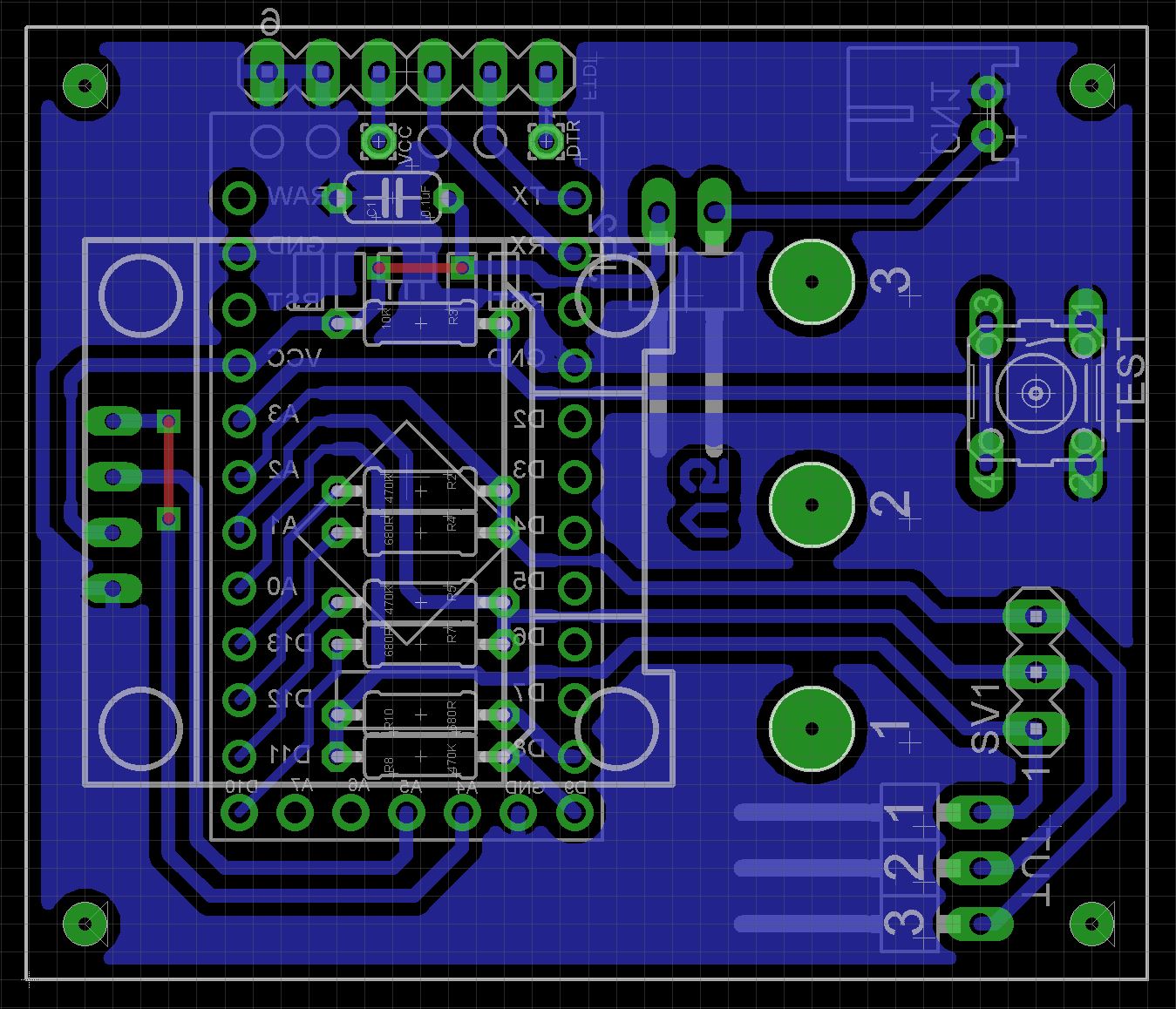
AssemblyI have included the Eagle files in case you want to get the board commercially made or do as I did and make it yourself. I used the Toner method.
Start by adding the links if your PCB is single-sided, resistors and the capacitor.
Next add the pin headers for the Arduino Pro Micro. Note there are two connections that go down to the PCB from where the FTDI pin header is normally connected (DTR and VCC). The actual FTDI pin header is along side and is mounted on the main PCB to reduce the overall height.
If you use a header on a single sided board, here is the method I use to add them.
Place header on PCB with longer pin side down, solder pins, push black plastic down towards the PCB.
Also add the right-angle 2 pin header for the switch connection and the JST socket for the battery connection.
Solder on the Arduino Mini Pro.
On the component side, add the 6mmx6mm tactile switch with a 6mm shaft, the 3 pin female machined header and the 3 pin right-angle Dupont header.
Glue a couple of supports for the OLED display. I used the plastic from a old pin header so that it matches the height of the pin header on the OLED display.
After the glue dries, solder on the OLED display.
Glue on the button top. Make sure the glue does not run down the shaft and into the switch.
Add the three 2mm Banana sockets. I used two 4mm washers on each socket. The bottom one had the wire soldered to it. Put a female Dupont connector on the other end and plug into the PCB.
Fix the PCB to the case using four M2 4mm screws.
Connect a FTDI programmer to the FTDI pin header.
In the Arduino IDE, select the settings as shown below and upload the sketch.
Finally add the battery and power switch and plug them into the PCB before closing the case.
The accuracy of this unit is not too bad. It is really good at identifying leads on transistors and that is what I will primarily use it for. I think it will make a useful addition to any toolbox.

  /*                      \\\|///
                        \\  - -  //
                         (  @ @  )
  /--------------------oOOo-(_)-oOOo---------------------\
  |                                                      |
  |                                                      |
  |    Transistor Tester for Arduino (version 1.08a)     |
  |                                                      |
  |  based on code: Karl-Heinz Kubbeler (version 1.08k)  |
  |                                                      |
  |                                                      |
  |                            Oooo                      |
  \--------------------oooO----(   )---------------------/
    	               (   )    ) /
                        \ (    (_/
                         \_)                            */


#include <avr/io.h>
#include <util/delay.h>
#include <avr/sleep.h>
#include <stdlib.h>
#include <string.h>
#include <avr/eeprom.h>
#include <avr/pgmspace.h>
#include <avr/wdt.h>
#include <avr/interrupt.h>
#include <math.h>
#include <stdint.h>
#include <avr/power.h>

//#define LCD1602
//#define LCD_I2C
//#define NOK5110
//#define OLED096
#define OLED_I2C

#ifdef LCD_I2C
  #ifndef LCD1602
    #define LCD1602
  #endif
#endif

#ifdef OLED_I2C
  #ifndef OLED096
    #define OLED096
  #endif
#endif

#ifdef LCD1602
  #ifdef LCD_I2C
    #include <Wire.h>
    #include <LiquidCrystal_I2C.h>
  #else
    #include <LiquidCrystal.h>
  #endif
#endif

#ifdef NOK5110
  #include <SPI.h>
  #include <Adafruit_GFX.h>
  #include <Adafruit_PCD8544.h>
#endif

#ifdef OLED096
  #include <SPI.h>
  #include <Wire.h>
  #include <Adafruit_GFX.h>
  #include <Adafruit_SSD1306.h>
  #define TOP_ROW 4
#endif


// ******** config options for your Semiconductor tester

// Every changing of this Makefile will result in new compiling the whole
// programs, if you call make or make upload.

#define MCU atmega328p
#define F_CPU 16000000UL

// Select your language:
// Available languages are: LANG_ENGLISH, LANG_GERMAN, LANG_POLISH, LANG_CZECH, LANG_SLOVAK, LANG_SLOVENE,
//                          LANG_DUTCH, LANG_BRASIL, LANG_RUSSIAN, LANG_UKRAINIAN
#define LANG_ENGLISH

// The LCD_CYRILLIC option is necessary, if you have a display with cyrillic characterset.
// This lcd-display don't have a character for Ohm and for u (micro).
// Russian language requires a LCD controller with russian characterset and option LCD_CYRILLIC!
#define LCD_CYRILLIC

// The LCD_DOGM option must be set for support of the DOG-M type of LCD modules with ST7036 controller.
// For this LCD type the contrast must be set with software command.
//#define LCD_DOGM

// Option STRIP_GRID_BOARD selects different board-layout, do not set for standard board!
// The connection of LCD is totally different for both versions.
//#define STRIP_GRID_BOARD

// The WITH_SELFTEST option enables selftest function (only for mega168 or mega328).
//#define WITH_SELFTEST

// AUTO_CAL will enable the autocalibration of zero offset of capacity measurement and
// also the port output resistance values will be find out in SELFTEST section.
// With a external capacitor a additionally correction of reference voltage is figured out for
// low capacity measurement and also for the AUTOSCALE_ADC measurement.
// The AUTO_CAL option is only selectable for mega168 and mega328.
//#define AUTO_CAL

// FREQUENCY_50HZ enables a 50 Hz frequency generator for up to one minute at the end of selftests.
//#define FREQUENCY_50HZ

// The WITH_AUTO_REF option enables reading of internal REF-voltage to get factors for the Capacity measuring.
#define WITH_AUTO_REF
// REF_C_KORR corrects the reference Voltage for capacity measurement (<40uF) and has mV units.
// Greater values gives lower capacity results.
#define REF_C_KORR 12
// REF_L_KORR corrects the reference Voltage for inductance measurement and has mV units.
#define REF_L_KORR 40
// C_H_KORR defines a correction of 0.1% units for big capacitor measurement.
// Positive values will reduce measurement results.
#define C_H_KORR 0

// The WITH_UART option enables the software UART (TTL level output at Pin PC3, 26).
// If the option is deselected, PC3 can be used as external voltage input with a
// 10:1 resistor divider.
//#define WITH_UART

// The CAP_EMPTY_LEVEL  defines the empty voltage level for capacitors in mV.
// Choose a higher value, if your Tester reports "Cell!" by unloading capacitors.
#define CAP_EMPTY_LEVEL 4

// The AUTOSCALE_ADC option enables the autoscale ADC (ADC use VCC and Bandgap Ref).
#define AUTOSCALE_ADC
#define REF_R_KORR 3

// The ESR_ZERO value define the zero value of ESR measurement (units = 0.01 Ohm).
//#define ESR_ZERO 29
#define ESR_ZERO 20

// NO_AREF_CAP tells your Software, that you have no Capacitor installed at pin AREF (21).
// This enables a shorter wait-time for AUTOSCALE_ADC function.
// A capacitor with 1nF can be used with the option NO_AREF_CAP set.
#define NO_AREF_CAP

// The OP_MHZ option tells the software the Operating Frequency of your ATmega.
// OP_MHZ 16

// Restart from sleep mode will be delayed for 16384 clock tics with crystal mode.
// Operation with the internal RC-Generator or external clock will delay the restart by only 6 clock tics.
// You must specify this with "#define RESTART_DELAY_TICS=6", if you don't use the crystal mode.
//#define RESTART_DELAY_TICS 6

// The USE_EEPROM option specify where you wish to locate fix text and tables.
// If USE_EEPROM is unset, program memory (flash) is taken for fix text and tables.
//#define USE_EEPROM

// Setting EBC_STYPE will select the old style to present the order of Transistor connection (EBC=...).
// Omitting the option will select the 123=... style.  Every point is replaced by a character identifying
// type of connected transistor pin (B=Base, E=Emitter, C=Collector, G=Gate, S=Source, D=Drain).
// If you select EBC_STYLE=321 , the style will be 321=... , the inverted order to the 123=... style.
//#define EBC_STYLE
//#define EBC_STYLE 321

// Setting of NO_NANO avoids the use of n as prefix for Farad (nF), the mikro prefix is used insted (uF).
//#define NO_NANO

// The PULLUP_DISABLE option disable the pull-up Resistors of IO-Ports.
// To use this option a external pull-up Resistor (10k to 30k)
// from Pin 13 to VCC must be installed!
#define PULLUP_DISABLE

// The ANZ_MESS option specifies, how often an ADC value is read and accumulated.
// Possible values of ANZ_MESS are 5 to 200.
#define ANZ_MESS 25

// The POWER_OFF option enables the power off function, otherwise loop measurements infinitely
// until power is disconnected with a ON/OFF switch (#define POWER_OFF).
// If you have the tester without the power off transistors, you can deselect POWER_OFF .
// If you have NOT selected the POWER_OFF option with the transistors installed,
// you can stop measuring by holding the key several seconds after a result is
// displayed. After releasing the key, the tester will be shut off by timeout.
// Otherwise you can also specify, after how many measurements without found part
// the tester will shut down (#define POWER_OFF=5).
// The tester will also shut down with found part,
// but successfull measurements are allowed double of the specified number.
// You can specify up to 255 empty measurements (#define POWER_OFF=255).
//#define POWER_OFF 5
//#define POWER_OFF

// Option BAT_CHECK enables the Battery Voltage Check, otherwise the SW Version is displayed instead of Bat.
// BAT_CHECK should be set for battery powered tester version.
//#define BAT_CHECK

// The BAT_OUT option enables Battery Voltage Output on LCD (if BAT_CHECK is selected).
// If your 9V supply has a diode installed, use the BAT_OUT=600 form to specify the
// threshold voltage of your diode to adjust the output value.
// This threshold level is added to LCD-output and does not affect the voltage checking levels.
//#define BAT_OUT 150

// To adjust the warning-level and poor-level of battery check to the capability of a
// low drop voltage regulator, you can specify the Option BAT_POOR=5400 .
// The unit for this option value is 1mV , 5400 means a poor level of 5.4V.
// The warning level is 0.8V higher than the specified poor level (>5.3V).
// The warning level is 0.4V higher than the specified poor level (>2.9V, <=5.3V).
// The warning level is 0.2V higher than the specified poor level (>1.3V, <=2.9V).
// The warning level is 0.1V higher than the specified poor level (<=1.3V).
// Setting the poor level to low values is not recommended for rechargeable Batteries,
// because this increase the danger for deep discharge!!
#define BAT_POOR 6400

// The sleep mode of the ATmega168 or ATmega328 is normally used by the software to save current.
// You can inhibit this with the option INHIBIT_SLEEP_MODE .
//#define INHIBIT_SLEEP_MODE

// ******** end of selectable options

/* -=- -=- -=- -=- -=- -=- -=- -=- -=- -=- -=- -=- -=- -=- -=- -=- -=- -=- -=- -=- -=- -=- -=- -=- -=- -=- -=- -=- */

// ########  Configuration

#ifndef ADC_PORT
//#define DebugOut 3		// if set, output of voltages of resistor measurements in row 2,3,4
//#define DebugOut 4		// if set, output of voltages of Diode measurement in row 3+4
//#define DebugOut 5		// if set, output of Transistor checks in row 2+3
//#define DebugOut 10		// if set, output of capacity measurements (ReadCapacity) in row 3+4

/*
  Port, that is directly connected to the probes.
  This Port must have an ADC-Input  (ATmega8:  PORTC).
  The lower pins of this Port must be used for measurements.
  Please don't change the definitions of TP1, TP2 and TP3!
  The TPREF pin can be connected with a 2.5V precision voltage reference
  The TPext can be used with a 10:1 resistor divider as external voltage probe up to 50V
*/

#define ADC_PORT PORTC
#define ADC_DDR DDRC
#define ADC_PIN PINC
#define TP1 0
#define TP2 1
#define TP3 2
#define TPext 3
// Port pin for 2.5V precision reference used for VCC check (optional)
#define TPREF 4
// Port pin for Battery voltage measuring
#define TPBAT 5

/*
  exact values of used resistors (Ohm).
  The standard value for R_L is 680 Ohm, for R_H 470kOhm.

  To calibrate your tester the resistor-values can be adjusted:
*/
#define R_L_VAL 6800          // standard value 680 Ohm, multiplied by 10 for 0.1 Ohm resolution
//#define R_L_VAL 6690        // this will be define a 669 Ohm
#define R_H_VAL 47000         // standard value 470000 Ohm, multiplied by 10, divided by 100
//#define R_H_VAL 47900       // this will be define a 479000 Ohm, divided by 100

#define R_DDR DDRB
#define R_PORT PORTB

/*
  Port for the Test resistors
  The Resistors must be connected to the lower 6 Pins of the Port in following sequence:
  RLx = 680R-resistor for Test-Pin x
  RHx = 470k-resistor for Test-Pin x

  RL1 an Pin 0
  RH1 an Pin 1
  RL2 an Pin 2
  RH2 an Pin 3
  RL3 an Pin 4
  RH3 an Pin 5
*/

#define ON_DDR DDRD
#define ON_PORT PORTD
#define ON_PIN_REG PIND
#define ON_PIN 18               // Pin, must be switched to high to switch power on

#ifdef STRIP_GRID_BOARD
// Strip Grid board version
  #define RST_PIN 0             // Pin, is switched to low, if push button is pressed
#else
// normal layout version
  #define RST_PIN 17            // Pin, is switched to low, if push button is pressed
#endif


// Port(s) / Pins for LCD

#ifdef STRIP_GRID_BOARD
  // special Layout for strip grid board
  #define HW_LCD_EN_PORT         PORTD
  #define HW_LCD_EN_PIN          5

  #define HW_LCD_RS_PORT         PORTD
  #define HW_LCD_RS_PIN          7

  #define HW_LCD_B4_PORT         PORTD
  #define HW_LCD_B4_PIN          4
  #define HW_LCD_B5_PORT         PORTD
  #define HW_LCD_B5_PIN          3
  #define HW_LCD_B6_PORT         PORTD
  #define HW_LCD_B6_PIN          2
  #define HW_LCD_B7_PORT         PORTD
  #define HW_LCD_B7_PIN          1
#else
  // normal Layout
  #define HW_LCD_EN_PORT         PORTD
  #define HW_LCD_EN_PIN          6

  #define HW_LCD_RS_PORT         PORTD
  #define HW_LCD_RS_PIN          7

  #define HW_LCD_B4_PORT         PORTD
  #define HW_LCD_B4_PIN          5
  #define HW_LCD_B5_PORT         PORTD
  #define HW_LCD_B5_PIN          4
  #define HW_LCD_B6_PORT         PORTD
  #define HW_LCD_B6_PIN          3
  #define HW_LCD_B7_PORT         PORTD
  #define HW_LCD_B7_PIN          2
#endif


// U_VCC defines the VCC Voltage of the ATmega in mV units

#define U_VCC 5000
// integer factors are used to change the ADC-value to mV resolution in ReadADC !

// With the option NO_CAP_HOLD_TIME you specify, that capacitor loaded with 680 Ohm resistor will not
// be tested to hold the voltage same time as load time.
// Otherwise (without this option) the voltage drop during load time is compensated to avoid displaying
// too much capacity for capacitors with internal parallel resistance.
// #define NO_CAP_HOLD_TIME


// U_SCALE can be set to 4 for better resolution of ReadADC function for resistor measurement
#define U_SCALE 4

// R_ANZ_MESS can be set to a higher number of measurements (up to 200) for resistor measurement
#define R_ANZ_MESS 190

// Watchdog
//#define WDT_enabled
/*
  If you remove the "#define WDT_enabled" , the Watchdog will not be activated.
  This is only for Test or debugging usefull.
  For normal operation please activate the Watchdog !
*/

// ########  End of configuration


#if R_ANZ_MESS < ANZ_MESS
  #undef R_ANZ_MESS
  #define R_ANZ_MESS ANZ_MESS
#endif
#if U_SCALE < 0
  // limit U_SCALE
  #undef U_SCALE
  #define U_SCALE 1
#endif
#if U_SCALE > 4
  // limit U_SCALE
  #undef U_SCALE
  #define U_SCALE 4
#endif
#ifndef REF_L_KORR
  #define REF_L_KORR 50
#endif


// the following definitions specify where to load external data from: EEprom or flash
#ifdef USE_EEPROM
  #define MEM_TEXT EEMEM

  #if E2END > 0X1FF
    #define MEM2_TEXT EEMEM
    #define MEM2_read_byte(a)  eeprom_read_byte(a)
    #define MEM2_read_word(a)  eeprom_read_word(a)
    #define lcd_fix2_string(a)  lcd_fix_string(a)
  #else
    #define MEM2_TEXT PROGMEM
    #define MEM2_read_byte(a)  pgm_read_byte(a)
    #define MEM2_read_word(a)  pgm_read_word(a)
    #define lcd_fix2_string(a)  lcd_pgm_string(a)
    #define use_lcd_pgm
  #endif

  #define MEM_read_word(a)  eeprom_read_word(a)
  #define MEM_read_byte(a)  eeprom_read_byte(a)

#else
  #define MEM_TEXT PROGMEM
  #define MEM2_TEXT PROGMEM
  #define MEM_read_word(a)  pgm_read_word(a)
  #define MEM_read_byte(a)  pgm_read_byte(a)
  #define MEM2_read_byte(a)  pgm_read_byte(a)
  #define MEM2_read_word(a)  pgm_read_word(a)
  #define lcd_fix2_string(a)  lcd_pgm_string(a)
  #define use_lcd_pgm
#endif


// RH_OFFSET : systematic offset of resistor measurement with RH (470k)
// resolution is 0.1 Ohm, 3500 defines a offset of 350 Ohm
#define RH_OFFSET 3500

// TP2_CAP_OFFSET is a additionally offset for TP2 capacity measurements in pF units
#define TP2_CAP_OFFSET 2

// CABLE_CAP defines the capacity (pF) of 12cm cable with clip at the terminal pins
#define CABLE_CAP 3


// select the right Processor Typ
/*
#if defined(__AVR_ATmega48__)
  #define PROCESSOR_TYP 168
#elif defined(__AVR_ATmega48P__)
  #define PROCESSOR_TYP 168
#elif defined(__AVR_ATmega88__)
  #define PROCESSOR_TYP 168
#elif defined(__AVR_ATmega88P__)
  #define PROCESSOR_TYP 168
#elif defined(__AVR_ATmega168__)
  #define PROCESSOR_TYP 168
#elif defined(__AVR_ATmega168P__)
  #define PROCESSOR_TYP 168
#elif defined(__AVR_ATmega328__)
  #define PROCESSOR_TYP 328
#elif defined(__AVR_ATmega328P__)
  #define PROCESSOR_TYP 328
#elif defined(__AVR_ATmega640__)
  #define PROCESSOR_TYP 1280
#elif defined(__AVR_ATmega1280__)
  #define PROCESSOR_TYP 1280
#elif defined(__AVR_ATmega2560__)
  #define PROCESSOR_TYP 1280
#else
  #define PROCESSOR_TYP 8
#endif
*/
#define PROCESSOR_TYP 328


// automatic selection of right call type
#if FLASHEND > 0X1FFF
  #define ACALL call
#else
  #define ACALL rcall
#endif


// automatic selection of option and parameters for different AVRs

//------------------=========----------
#if PROCESSOR_TYP == 168
//------------------=========----------
  #define MCU_STATUS_REG MCUCR
  #define ADC_COMP_CONTROL ADCSRB
  #define TI1_INT_FLAGS TIFR1
  #define DEFAULT_BAND_GAP 1070
  #define DEFAULT_RH_FAKT  884      // mega328 1070 mV
  // LONG_HFE  activates computation of current amplification factor with long variables
  #define LONG_HFE
  // COMMON_COLLECTOR activates measurement of current amplification factor in common collector circuit  (Emitter follower)
  #define COMMON_COLLECTOR
  #define MEGA168A 17
  #define MEGA168PA 18

  // Pin resistor values of ATmega168
  //#define PIN_RM 196
  //#define PIN_RP 225
  #define PIN_RM 190
  #define PIN_RP 220
  // CC0 defines the capacity of empty terminal pins 1 & 3 without cable
  #define CC0 36
  // Slew rate correction  val += COMP_SLEW1 / (val + COMP_SLEW2)
  #define COMP_SLEW1 4000
  #define COMP_SLEW2 220
  #define C_NULL CC0+CABLE_CAP+(COMP_SLEW1 / (CC0 + CABLE_CAP + COMP_SLEW2))
  #define MUX_INT_REF 0x0e	// channel number of internal 1.1 V

//------------------=========----------
#elif PROCESSOR_TYP == 328
//------------------=========----------
  #define MCU_STATUS_REG MCUCR
  #define ADC_COMP_CONTROL ADCSRB
  #define TI1_INT_FLAGS TIFR1
  #define DEFAULT_BAND_GAP 1070
  #define DEFAULT_RH_FAKT  884      // mega328 1070 mV
  // LONG_HFE  activates computation of current amplification factor with long variables
  #define LONG_HFE
  // COMMON_COLLECTOR activates measurement of current amplification factor in common collector circuit  (Emitter follower)
  #define COMMON_COLLECTOR

  #define PIN_RM 200
  #define PIN_RP 220
  // CC0 defines the capacity of empty terminal pins 1 & 3 without cable
  #define CC0 36
  // Slew rate correction  val += COMP_SLEW1 / (val + COMP_SLEW2)
  #define COMP_SLEW1 4000
  #define COMP_SLEW2 180
  #define C_NULL CC0+CABLE_CAP+(COMP_SLEW1 / (CC0 + CABLE_CAP + COMP_SLEW2))
  #define MUX_INT_REF 0x0e	// channel number of internal 1.1 V

//------------------=========----------
#elif PROCESSOR_TYP == 1280
//------------------=========----------
  #define MCU_STATUS_REG MCUCR
  #define ADC_COMP_CONTROL ADCSRB
  #define TI1_INT_FLAGS TIFR1
  #define DEFAULT_BAND_GAP 1070
  #define DEFAULT_RH_FAKT  884      // mega328 1070 mV
  // LONG_HFE  activates computation of current amplification factor with long variables
  #define LONG_HFE
  // COMMON_COLLECTOR activates measurement of current amplification factor in common collector circuit  (Emitter follower)
  #define COMMON_COLLECTOR

  #define PIN_RM 200
  #define PIN_RP 220
  // CC0 defines the capacity of empty terminal pins 1 & 3 without cable
  #define CC0 36
  // Slew rate correction  val += COMP_SLEW1 / (val + COMP_SLEW2)
  #define COMP_SLEW1 4000
  #define COMP_SLEW2 180
  #define C_NULL CC0+CABLE_CAP+(COMP_SLEW1 / (CC0 + CABLE_CAP + COMP_SLEW2))
  #define MUX_INT_REF 0x1e	/* channel number of internal 1.1 V */

//------------------=========----------
#else
//                   ATmega8
//------------------=========----------
  #define MCU_STATUS_REG MCUCSR
  #define ADC_COMP_CONTROL SFIOR
  #define TI1_INT_FLAGS TIFR
  #define DEFAULT_BAND_GAP 1298		//mega8 1298 mV
  #define DEFAULT_RH_FAKT  740      // mega8 1250 mV
  // LONG_HFE  activates computation of current amplification factor with long variables
  #define LONG_HFE
  // COMMON_COLLECTOR activates measurement of current amplification factor in common collector circuit  (Emitter follower)
  #define COMMON_COLLECTOR

  #define PIN_RM 196
  #define PIN_RP 240
  // CC0 defines the capacity of empty terminal pins 1 & 3 without cable
  #define CC0 27
  // Slew rate correction  val += COMP_SLEW1 / (val + COMP_SLEW2)
  #define COMP_SLEW1 0
  #define COMP_SLEW2 33
  #define C_NULL CC0+CABLE_CAP+(COMP_SLEW1 / (CC0 + CABLE_CAP + COMP_SLEW2))
  #define MUX_INT_REF 0x0e	/* channel number of internal 1.1 V */

  #ifndef INHIBIT_SLEEP_MODE
    #define INHIBIT_SLEEP_MODE	/* do not use the sleep mode of ATmega */
  #endif
#endif

#if PROCESSOR_TYP == 8
  // 2.54V reference voltage + correction (fix for ATmega8)
  #ifdef AUTO_CAL
    #define ADC_internal_reference (2560 + (int8_t)eeprom_read_byte((uint8_t *)&RefDiff))
  #else
    #define ADC_internal_reference (2560 + REF_R_KORR)
  #endif
#else
  // all other processors use a 1.1V reference
  #ifdef AUTO_CAL
    #define ADC_internal_reference (ref_mv + (int8_t)eeprom_read_byte((uint8_t *)&RefDiff))
  #else
    #define ADC_internal_reference (ref_mv + REF_R_KORR)
  #endif
#endif


#ifndef REF_R_KORR
  #define REF_R_KORR 0
#endif
#ifndef REF_C_KORR
  #define REF_C_KORR 0
#endif

#define LONG_WAIT_TIME 28000
#define SHORT_WAIT_TIME 5000

#ifdef POWER_OFF
  // if POWER OFF function is selected, wait 14s
  // if POWER_OFF with parameter > 2, wait only 5s before repeating
  #if (POWER_OFF+0) > 2
    #define OFF_WAIT_TIME SHORT_WAIT_TIME
  #else
    #define OFF_WAIT_TIME LONG_WAIT_TIME
  #endif
#else
  // if POWER OFF function is not selected, wait 14s before repeat measurement
  #define OFF_WAIT_TIME  LONG_WAIT_TIME
#endif


//**********************************************************
// defines for the selection of a correctly  ADC-Clock
// will match for 1MHz, 2MHz, 4MHz, 8MHz and 16MHz
// ADC-Clock can be 125000 or 250000
// 250 kHz is out of the full accuracy specification!
// clock divider is 4, when CPU_Clock==1MHz and ADC_Clock==250kHz
// clock divider is 128, when CPU_Clock==16MHz and ADC_Clock==125kHz
#define F_ADC 125000
//#define F_ADC 250000
#if F_CPU/F_ADC == 2
  #define AUTO_CLOCK_DIV (1<<ADPS0)
#endif
#if F_CPU/F_ADC == 4
  #define AUTO_CLOCK_DIV (1<<ADPS1)
#endif
#if F_CPU/F_ADC == 8
  #define AUTO_CLOCK_DIV (1<<ADPS1) | (1<<ADPS0)
#endif
#if F_CPU/F_ADC == 16
  #define AUTO_CLOCK_DIV (1<<ADPS2)
#endif
#if F_CPU/F_ADC == 32
  #define AUTO_CLOCK_DIV (1<<ADPS2) | (1<<ADPS0)
#endif
#if F_CPU/F_ADC == 64
  #define AUTO_CLOCK_DIV (1<<ADPS2) | (1<<ADPS1)
#endif
#if F_CPU/F_ADC == 128
  #define AUTO_CLOCK_DIV (1<<ADPS2) | (1<<ADPS1) | (1<<ADPS0)
#endif
//**********************************************************
#define F_ADC_F 500000
#if F_CPU/F_ADC_F == 2
  #define FAST_CLOCK_DIV (1<<ADPS0)
#endif
#if F_CPU/F_ADC_F == 4
  #define FAST_CLOCK_DIV (1<<ADPS1)
#endif
#if F_CPU/F_ADC_F == 8
  #define FAST_CLOCK_DIV (1<<ADPS1) | (1<<ADPS0)
#endif
#if F_CPU/F_ADC_F == 16
  #define FAST_CLOCK_DIV (1<<ADPS2)
#endif
#if F_CPU/F_ADC_F == 32
  #define FAST_CLOCK_DIV (1<<ADPS2) | (1<<ADPS0)
#endif
#if F_CPU/F_ADC_F == 64
  #define FAST_CLOCK_DIV (1<<ADPS2) | (1<<ADPS1)
#endif
#if F_CPU/F_ADC_F == 128
  #define FAST_CLOCK_DIV (1<<ADPS2) | (1<<ADPS1) | (1<<ADPS0)
#endif


#ifndef PIN_RP
  #define PIN_RP  220           // estimated internal resistance PORT to VCC
                                // will only be used, if not set before in config.h
#endif
#ifndef PIN_RM
  #define PIN_RM  190           // estimated internal resistance PORT to GND
                                // will only be used, if not set before in config.h
#endif

//**********************************************************

// defines for the WITH_UART option
/*
With define SWUART_INVERT you can specify, if the software-UART operates normal or invers.
in the normal mode the UART sends with usual logik level (Low = 0; High = 1).
You can use this mode for direct connection to a uC, or a level converter like MAX232.

With invers mode the UART sends with invers logik (Low = 1, High = 0).
This is the level of a standard RS232 port of a PC.
In most cases the output of the software UART can so be connected to the RxD of a PC.
The specification say, that level -3V to 3V is unspecified, but in most cases it works.
Is a simple but unclean solution.

Is SWUART_INVERT defined, the UART works is inverse mode
*/
//#define SWUART_INVERT

#define TxD 3	  // TxD-Pin of Software-UART; must be at Port C !
#ifdef WITH_UART
  #define TXD_MSK (1<<TxD)
#else
  #define TXD_MSK 0xF8
#endif

#ifdef SWUART_INVERT
  #define TXD_VAL 0
#else
  #define TXD_VAL TXD_MSK
#endif


#ifdef INHIBIT_SLEEP_MODE
  // save memory, do not use the sleep mode
  #define wait_about5ms() wait5ms()
  #define wait_about10ms() wait10ms()
  #define wait_about20ms() wait20ms()
  #define wait_about30ms() wait30ms()
  #define wait_about50ms() wait50ms()
  #define wait_about100ms() wait100ms()
  #define wait_about200ms() wait200ms()
  #define wait_about300ms() wait300ms()
  #define wait_about400ms() wait400ms()
  #define wait_about500ms() wait500ms()
  #define wait_about1s() wait1s()
  #define wait_about2s() wait2s()
  #define wait_about3s() wait3s()
  #define wait_about4s() wait4s()
#else
  // use sleep mode to save current for user interface
  #define wait_about5ms() sleep_5ms(1)
  #define wait_about10ms() sleep_5ms(2)
  #define wait_about20ms() sleep_5ms(4)
  #define wait_about30ms() sleep_5ms(6)
  #define wait_about50ms() sleep_5ms(10)
  #define wait_about100ms() sleep_5ms(20)
  #define wait_about200ms() sleep_5ms(40)
  #define wait_about300ms() sleep_5ms(60)
  #define wait_about400ms() sleep_5ms(80)
  #define wait_about500ms() sleep_5ms(100)
  #define wait_about1s() sleep_5ms(200)
  #define wait_about2s() sleep_5ms(400)
  #define wait_about3s() sleep_5ms(600)
  #define wait_about4s() sleep_5ms(800)
#endif


#undef AUTO_RH
#ifdef WITH_AUTO_REF
  #define AUTO_RH
#else
  #ifdef AUTO_CAL
    #define AUTO_RH
  #endif
#endif

#undef CHECK_CALL
#ifdef WITH_SELFTEST
  // AutoCheck Function is needed
  #define CHECK_CALL
#endif

#ifdef AUTO_CAL
  // AutoCheck Function is needed
  #define CHECK_CALL
  #define RR680PL resis680pl
  #define RR680MI resis680mi
  #define RRpinPL pin_rpl
  #define RRpinMI pin_rmi
#else
  #define RR680PL (R_L_VAL + PIN_RP)
  #define RR680MI (R_L_VAL + PIN_RM)
  #define RRpinPL (PIN_RP)
  #define RRpinMI (PIN_RM)
#endif

#ifndef ESR_ZERO
  // define a default zero value for ESR measurement (0.01 Ohm units)
  #define ESR_ZERO 20
#endif

#ifndef RESTART_DELAY_TICS
  // define the processor restart delay for crystal oscillator 16K
  // only set, if no preset (Makefile) exists.
  #define RESTART_DELAY_TICS 16384
  // for ceramic oscillator 258 or 1024 Clock tics can be selected with fuses
  // for external oscillator or RC-oscillator is only a delay of 6 clock tics.
#endif

// with EBC_STYLE you can select the Pin-description in EBC= style instead of 123=??? style
//#define EBC_STYLE
#if EBC_STYLE == 123
  // unset the option for the 123 selection, since this style is default.
  #undef EBC_STYLE
#endif


#if defined(NOK5110) || defined(OLED096)
  #define LCD_CHAR_DIODE1 0x91
  #define LCD_CHAR_DIODE2 0x92
  #define LCD_CHAR_CAP    0x93
  #define LCD_CHAR_RESIS1 0x94
  #define LCD_CHAR_RESIS2 0x95
  #define LCD_CHAR_OMEGA  0x90
  #define LCD_CHAR_U      0xB5

#else
  // self build characters
  #define LCD_CHAR_DIODE1  1      // Diode-Icon; will be generated as custom character
  #define LCD_CHAR_DIODE2  2      // Diode-Icon; will be generated as custom character
  #define LCD_CHAR_CAP 3          // Capacitor-Icon;  will be generated as custom character
  // numbers of RESIS1 and RESIS2 are swapped for OLED display, which shows a corrupt RESIS1 character otherwise ???
  #define LCD_CHAR_RESIS1 7       // Resistor left part will be generated as custom character
  #define LCD_CHAR_RESIS2 6       // Resistor right part will be generated as custom character

  #ifdef LCD_CYRILLIC
    #define LCD_CHAR_OMEGA  4       // Omega-character
    #define LCD_CHAR_U  5           // micro-character
  #else
    #define LCD_CHAR_OMEGA  244     // Omega-character
    #define LCD_CHAR_U  228         // micro-character
  #endif

  #ifdef LCD_DOGM
    #undef LCD_CHAR_OMEGA
    #define LCD_CHAR_OMEGA 0x1e     // Omega-character for DOGM module
    #undef LCD_CHAR_U
    #define LCD_CHAR_U  5           // micro-character for DOGM module loadable
  #endif

  #define LCD_CHAR_DEGREE 0xdf      // Character for degree
#endif

#endif  // #ifndef ADC_PORT


// the hFE (B) can be determined with common collector and common emitter circuit
// with more than 16K both methodes are possible
#ifdef COMMON_COLLECTOR
  #if FLASHEND > 0x3fff
    #define COMMON_EMITTER
  #endif
#else
  #define COMMON_EMITTER
#endif

/* -=- -=- -=- -=- -=- -=- -=- -=- -=- -=- -=- -=- -=- -=- -=- -=- -=- -=- -=- -=- -=- -=- -=- -=- -=- -=- -=- -=- */

#define MAIN_C

#if defined (MAIN_C)
  #define COMMON
  /*
  The voltage at a capacitor grows with  Uc = VCC * (1 - e**(-t/T))
  The voltage 1.3V is reached at  t = -ln(3.7/5)*T  = 0.3011*T .
  Time constant is  T = R * C ; also
  C = T / R
  for the resistor 470 kOhm  is C = t / (0.3011 * 470000)
  H_Fakt = 707/100 for a result in pF units.
  */

// Big Capacities (>50uF) are measured with up to 500 load-pulses with the 680 Ohm resistor.
// Each  of this load-puls has an length of 10ms. After every load-pulse the voltage of the
// capacitor is measured. If the voltage is more than 300mV, the capacity is computed by
// interpolating the corresponding values of the table RLtab and multiply that with the number
// of load pulses (*10).

// Widerstand 680 Ohm                300   325   350   375   400   425   450   475   500   525   550   575   600   625   650   675   700   725   750   775   800   825   850   875   900   925   950   975  1000  1025  1050  1075  1100  1125  1150  1175  1200  1225  1250  1275  1300  1325  1350  1375  1400  mV
const uint16_t RLtab[] MEM_TEXT = {22447,20665,19138,17815,16657,15635,14727,13914,13182,12520,11918,11369,10865,10401, 9973, 9577, 9209, 8866, 8546, 8247, 7966, 7702, 7454, 7220, 6999, 6789, 6591, 6403, 6224, 6054, 5892, 5738, 5590, 5449, 5314, 5185, 5061, 4942, 4828, 4718, 4613, 4511, 4413, 4319, 4228};

#if FLASHEND > 0x1fff
  //                                {0, 1, 2, 3, 4, 5, 6, 7, 8, 9, 10, 11, 12, 13, 14, 15, 16, 17, 18, 19, 20, 21, 22, 23, 24, 25, 26, 27, 28, 29, 30, 31, 32, 33, 34, 35, 36, 37, 38, 39, 40, 41, 42, 43, 44, 45, 46, 47, 48, 49, 50, 51, 52, 53, 54, 55, 56, 57, 58, 59, 60, 61, 62, 63,  64,  65,  66,  67,  68,  69,  70,  71,  72,  73,  74,  75,  76,  77,  78,  79,  80,  81,  82,  83,  84,  85,  86,  87,  88,  89,  90,  91 };
  const uint16_t LogTab[] PROGMEM = {0, 20, 41, 62, 83, 105, 128, 151, 174, 198, 223, 248, 274, 301, 329, 357, 386, 416, 446, 478, 511, 545, 580, 616, 654, 693, 734, 777, 821, 868, 916, 968, 1022, 1079, 1139, 1204, 1273, 1347, 1427, 1514, 1609, 1715, 1833, 1966, 2120, 2303, 2526 };
#endif

#ifdef AUTO_RH
  // resistor  470000 Ohm      1000 1050 1100 1150 1200 1250 1300 1350 1400  mV
  const uint16_t RHtab[] PROGMEM = { 954, 903, 856, 814, 775, 740, 707, 676, 648};
#endif

// with integer factors the ADC-value will be changed to mV resolution in ReadADC !
// all if statements are corrected to the mV resolution.


// Strings in PROGMEM or in EEprom

#if defined(LANG_GERMAN)		// deutsch
   const unsigned char TestRunning[] MEM_TEXT = "Testen...";
   const unsigned char BatWeak[] MEM_TEXT = "gering";
   const unsigned char BatEmpty[] MEM_TEXT = "leer!";
   const unsigned char TestFailed2[] MEM_TEXT = "defektes ";
   const unsigned char Component[] MEM_TEXT = "Bauteil";
//   const unsigned char Diode[] MEM_TEXT = "Diode: ";
   const unsigned char Triac[] MEM_TEXT = "Triac";
   const unsigned char Thyristor[] MEM_TEXT = "Thyristor";
   const unsigned char Unknown[] MEM_TEXT = " unbek.";
   const unsigned char TestFailed1[] MEM_TEXT = "Kein,unbek. oder";
   const unsigned char OrBroken[] MEM_TEXT = "oder defekt ";
   const unsigned char TestTimedOut[] MEM_TEXT = "Timeout!";
   #define Cathode_char 'K'
 #ifdef WITH_SELFTEST
   const unsigned char SELFTEST[] MEM_TEXT = "Selbsttest ..";
   const unsigned char RELPROBE[] MEM_TEXT = "isolate Probe!";
   const unsigned char ATE[] MEM_TEXT = "Test Ende";
 #endif
#endif

#if defined(LANG_ENGLISH)		// english
  const unsigned char TestRunning[] MEM_TEXT = "testing...";
  const unsigned char BatWeak[] MEM_TEXT = "weak";
  const unsigned char BatEmpty[] MEM_TEXT = "empty!";
  const unsigned char TestFailed2[] MEM_TEXT = "damaged ";
  const unsigned char Component[] MEM_TEXT = "part";
  //const unsigned char Diode[] MEM_TEXT = "Diode: ";
  const unsigned char Triac[] MEM_TEXT = "Triac";
  const unsigned char Thyristor[] MEM_TEXT = "Thyristor";
  const unsigned char Unknown[] MEM_TEXT = " unknown";
  const unsigned char TestFailed1[] MEM_TEXT = "No, unknown, or";
  const unsigned char OrBroken[] MEM_TEXT = "or damaged ";
  const unsigned char TestTimedOut[] MEM_TEXT = "Timeout!";
  #define Cathode_char 'C'

  #ifdef WITH_SELFTEST
    const unsigned char SELFTEST[] MEM_TEXT = "Selftest mode..";
    const unsigned char RELPROBE[] MEM_TEXT = "isolate Probe!";
    const unsigned char ATE[] MEM_TEXT = "Test End";
  #endif
#endif


// Strings, which are not dependent of any language
const unsigned char Bat_str[] MEM_TEXT = "Bat. ";
const unsigned char OK_str[] MEM_TEXT = "OK";
const unsigned char mosfet_str[] MEM_TEXT = "-MOS";
const unsigned char jfet_str[] MEM_TEXT = "JFET";
const unsigned char GateCap_str[] MEM_TEXT = "C=";
const unsigned char hfe_str[] MEM_TEXT ="B=";
const unsigned char NPN_str[] MEM_TEXT = "NPN ";
const unsigned char PNP_str[] MEM_TEXT = "PNP ";

#ifndef EBC_STYLE
  const unsigned char N123_str[] MEM_TEXT = " 123=";
  //const unsigned char N123_str[] MEM_TEXT = " Pin=";
#else
  #if EBC_STYLE == 321
    const unsigned char N321_str[] MEM_TEXT = " 321=";
  #endif
#endif

const unsigned char Uf_str[] MEM_TEXT = "Uf=";
const unsigned char vt_str[] MEM_TEXT = " Vt=";
const unsigned char Vgs_str[] MEM_TEXT = "@Vgs=";
const unsigned char CapZeich[] MEM_TEXT = {'-',LCD_CHAR_CAP,'-',0};
const unsigned char Cell_str[] MEM_TEXT = "Cell!";
const unsigned char VCC_str[] MEM_TEXT = "VCC=";

#if FLASHEND > 0x1fff
  const unsigned char ESR_str[] MEM_TEXT = " ESR=";
  const unsigned char VLOSS_str[] MEM_TEXT = " Vloss=";
  const unsigned char Lis_str[] MEM_TEXT = "L=";
  const unsigned char Ir_str[] MEM_TEXT = "  Ir=";

  #ifndef WITH_UART
    //#define WITH_VEXT
  #endif
#else
  #ifndef BAT_CHECK
    #ifndef WITH_UART
      //#define WITH_VEXT
    #endif
  #endif
#endif

#ifdef WITH_VEXT
  const unsigned char Vext_str[] MEM_TEXT = "Vext=";
  #define LCD_CLEAR
#endif


const unsigned char VERSION_str[] MEM2_TEXT = "Component Tester";

const unsigned char AnKat[] MEM_TEXT = {'-', LCD_CHAR_DIODE1, '-',0};
const unsigned char KatAn[] MEM_TEXT = {'-', LCD_CHAR_DIODE2, '-',0};
const unsigned char Diodes[] MEM_TEXT = {'*',LCD_CHAR_DIODE1, ' ', ' ',0};
const unsigned char Resistor_str[] MEM_TEXT = {'-', LCD_CHAR_RESIS1, LCD_CHAR_RESIS2,'-',0};

#ifdef WITH_SELFTEST
  const unsigned char URefT[] MEM2_TEXT = "Ref=";
  const unsigned char RHfakt[] MEM2_TEXT = "RHf=";
  const unsigned char RH1L[] MEM_TEXT = "RH-";
  const unsigned char RH1H[] MEM_TEXT = "RH+";
  const unsigned char RLRL[] MEM_TEXT = "+RL- 12 13 23";
  const unsigned char RHRH[] MEM_TEXT = "+RH- 12 13 23";
  const unsigned char RHRL[] MEM_TEXT = "RH/RL";
  const unsigned char R0_str[] MEM2_TEXT = "R0=";
  #define LCD_CLEAR
#endif

#ifdef CHECK_CALL
  const unsigned char RIHI[] MEM_TEXT = "Ri_Hi=";
  const unsigned char RILO[] MEM_TEXT = "Ri_Lo=";
  const unsigned char C0_str[] MEM_TEXT = "C0 ";
  const unsigned char T50HZ[] MEM_TEXT = " 50Hz";
#endif

#ifdef AUTO_CAL
  const unsigned char MinCap_str[] MEM2_TEXT = " >100nF";
  const unsigned char REF_C_str[] MEM2_TEXT = "REF_C=";
  const unsigned char REF_R_str[] MEM2_TEXT = "REF_R=";
#endif

#ifdef DebugOut
  #define LCD_CLEAR
...

This file has been truncated, please download it to see its full contents.


_3u05Tpwasz.png?auto=compress%2Cformat&w=40&h=40&fit=fillmax&bg=fff&dpr=2)
Comments