
Hardware components | ||||||
| × | 1 | ||||
| × | 1 | ||||
| × | 1 | ||||
| × | 3 | ||||
| × | 1 | ||||
| × | 1 | ||||
 |
| × | 1 | |||
Software apps and online services | ||||||
 |
| |||||
Hand tools and fabrication machines | ||||||
 |
| |||||
 |
| |||||
Many years ago I bought a fancy square 8x8 Matrix LED from Futurlec. They aren't expensive (around $2 each), they just seemed to be always out of stock whenever I ordered them. Anyway one did arrive and I have been keeping it for a special project so that I could show it off. This project seemed to be the right fit for it.
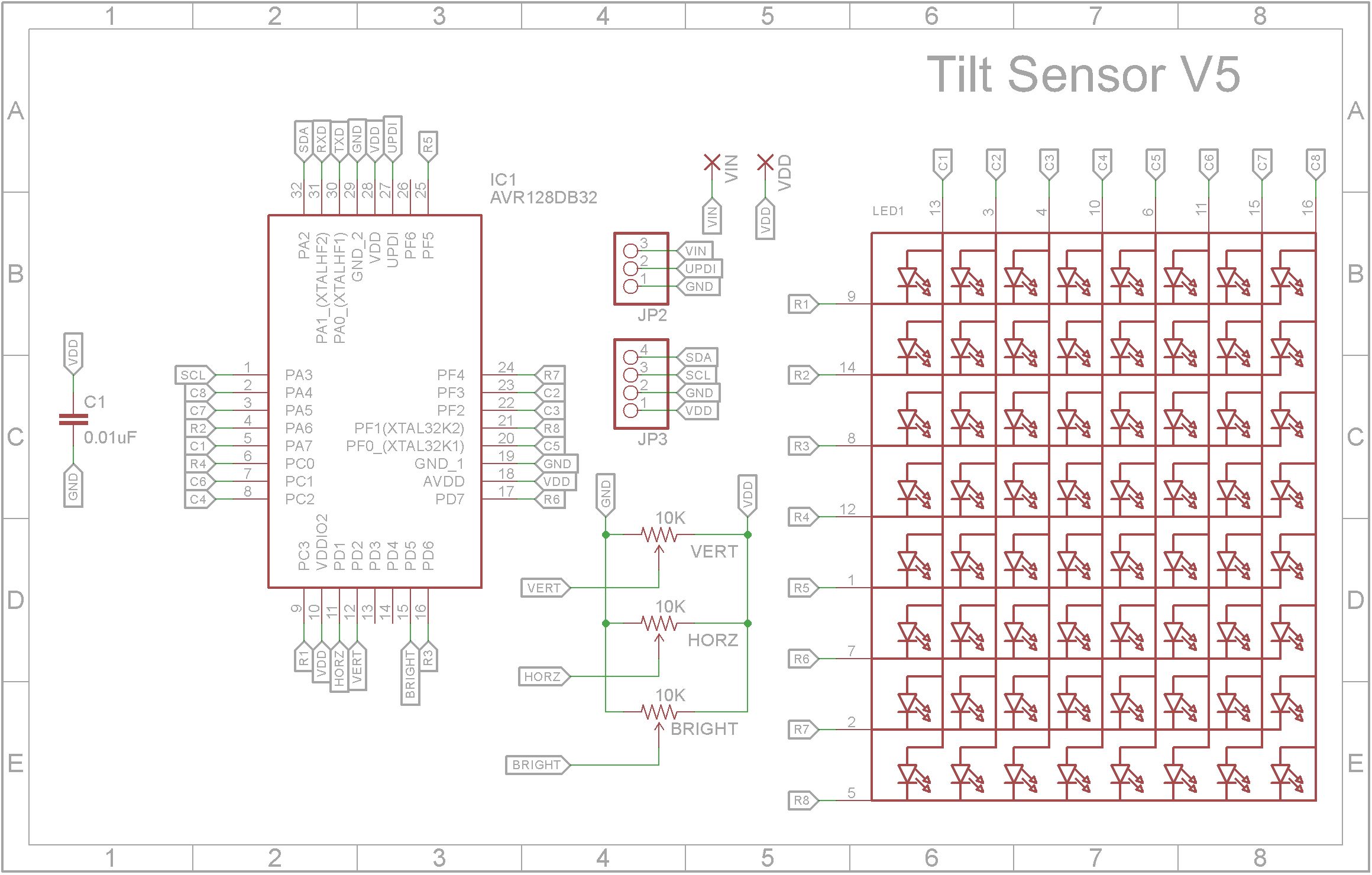
DemonstrationDesignMy primary goal when designing this project was keeping the size as small as possible. I didn't want it to be any wider than the LED matrix itself and being as thin as possible. Rather than use a MAX7219 driver chip like most display boards use to mange the LED matrix, I decided to use a AVR128DB32 microprocessor and have it control the matrix as well as processing the information coming from the MPU-6050 Motion Tracking Sensor.
As you can see from the above schematic, there are very few parts. The VERT and HORZ trim-pots ended up being redundant so you can leave them off your build if you wish.
There are no current limiting resistors. The amount of power to each LED is controlled in the software using a technique called Bit Angle Modulation or BAM for short. I tried to describe how this works in my Red/Green/Blue Disco Tile project. It performs in a similar manner to PWM.
The sensor used is a MPU-6050 Motion Tracking Sensor that is incorporated on the GY-521 module. This tracks movement and acceleration in all three planes and communicates to the microprocessor using the I2C protocol. This project only uses the values for the movement in the X and Y planes. The GY-521 module is mounted in the center of the board directly under the LED matrix.
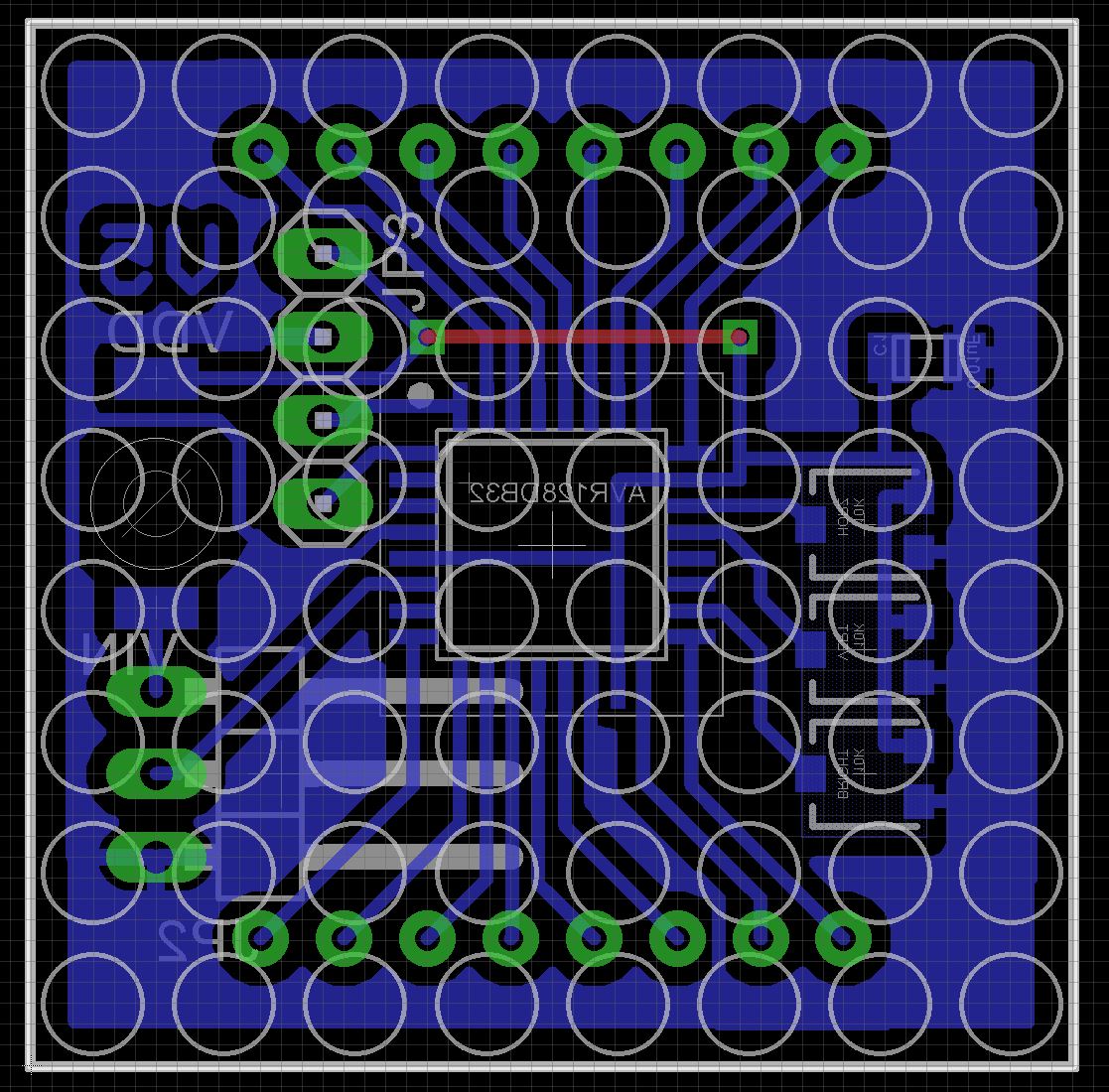
The PCBTo minimize the space required, the board has been designed to use Surface Mount Devices (SMD) where possible.
The Eagle files have been included should you wish to have the board commercially made or you can do as I did and make it yourself. I used the Toner method.
NOTE:
The following images shown in the assembly sections are for V4. I made a few mistakes like not realizing that port in PF6 on the AVR128DB32 microprocessor is INPUT only. Also the original plan to mount the mercury switch in the case didn't work out so now it is soldered to the PCB. Assembly however basically remains the same.
Assembly - Step 1Start by adding the SMD components. I find it easier to use solder paste rather than use solder from a reel when soldering SMD components. I also used my SMD reflow hot plate that I built a few months back to reflow the solder paste.
Add the link if your board is single-sided.
Add the 3 pin right angle male header that doubles as the connection for the programmer and also the battery. This is soldered to the copper side of the board.
Add the GY-521 module to the component side. You only need to connect the first four pins. The other 4 pins are not used.
Solder on the matrix ensuring it sits evenly. It won't go right down on the PCB because it hits the GY-521 module.
Add the mercury switch. It sits in the hole provided and the legs are soldered on the two adjacent pads. The leads are fragile and don't like too much bending.
At this point you should program the microprocessor. See next section.
Add a 3 pin Dupont male header to the battery wires and plug it into the PCB.
Programming the microprocessor is done using Serial UPDI. You probably don't have a Serial UPDI programmer, fortunately it is pretty easy to create one using off-the-self parts. Everything you need on how to build one is described in the following article by Spence Konde:
You need to install the DxCore into the Arduino IDE. This board package can be installed via the board manager. The boards manager URL is:
http://drazzy.com/package_drazzy.com_index.json
- File -> Preferences, enter the above URL in "Additional Boards Manager URLs"
- Tools -> Boards -> Boards Manager...
- Wait while the list loads (takes longer than one would expect, and refreshes several times).
- Select "DxCore" and click "Install".
Next open the sketch and select the AVR128DB32 microprocessor
Select Tools -> Board -> DxCore -> AVR DB Series (no bootloader)
Select Tools -> Chip-> AVR128DB32
Compile and upload the sketch.
ConclusionAn interesting project. The software part took a bit of work and this was the first time I used a AVR DB series microprocessor. I actually ended up building a dedicated Serial UPDI programmer which incorporates two USB-2-Serial convertors along with a USB Hub so I can program and receive serial data via the same USB cable.


Comments