/*
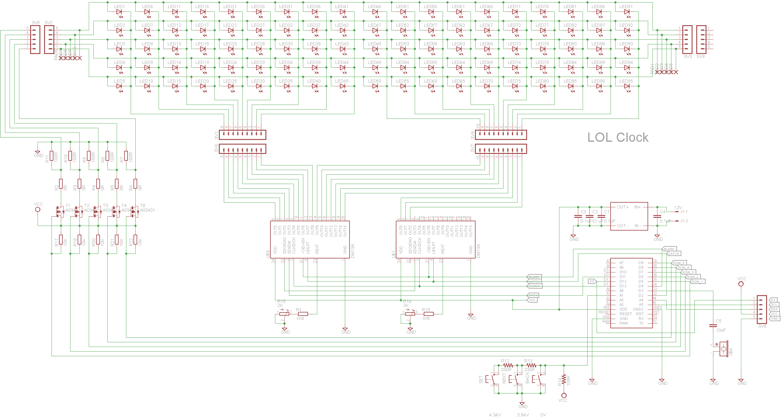
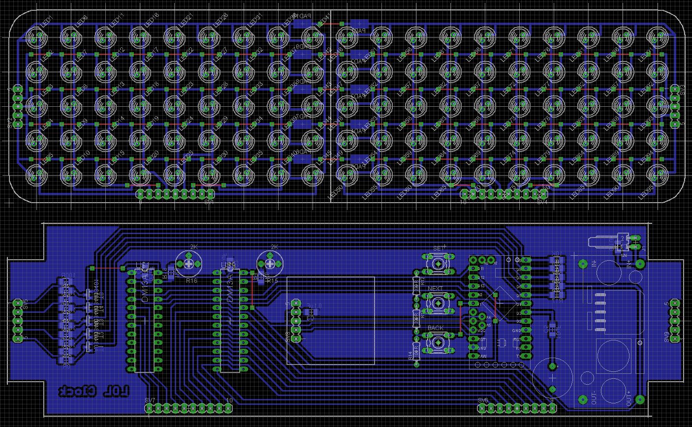
LOL Clock
19x5 LED matrix driven by two DM31A shift registers/LED drivers
DS1307 RTC
Three buttons on a single pin resistor network to set the time
Concept and Case: robaux (https://www.thingiverse.com/thing:2219658)
Schematic, Board design, Code: John Bradnam (jbrad2089@gmail.com)
*/
#include <SPI.h>// SPI Library used to clock data out to the shift registers
#include <Wire.h>
#include <RTClib.h>
#define LATCH_PIN 2 //can use any pin you want to latch the shift registers
#define BLANK_PIN 4 // same, can use any pin you want for this, just make sure you pull up via a 1k to 5V
#define DATA_PIN 11 // used by SPI, must be pin 11
#define CLOCK_PIN 13 // used by SPI, must be 13
#define ROW_1 5
#define ROW_2 6
#define ROW_3 7
#define ROW_4 8
#define ROW_5 9
//Buttons are on a resistor network
// A1 > 1000 (off)
// 850 <= A1 < 900 (MODE)
// 750 <= A1 < 800 (UP or NEXT)
// 0 <= A1 <= 50 (DOWN or PREV)
#define BUTTON_PIN A1
enum ButtonEnum { NO_BUTTON, MODE_BTN, UP_BTN, DOWN_BTN };
#define ROWS 5 //Number of rows of LEDs
#define LEDS_PER_ROW 24 //Number of bits to shift
#define BYTES_PER_ROW 4 //Number of bytes required to hold one bit per LED in each row
#define ACTUAL_OFFSET 8 //Offset to first LED
#define ACTUAL_PER_ROW 19 //Number of leds on each row
byte ledStates[ROWS][BYTES_PER_ROW]; //Store state of each LED (either off or on)
int activeRow=0; //this increments through the anode levels
//define modes to set time
enum ModeEnum { NORMAL, SET_HOURS, SET_MINUTES };
//Font characters use 20 bits and are stored as 3 bytes
//03 02 01 00
//07 06 05 04
//11 10 09 08
//15 14 13 12
//19 18 17 16
const uint8_t numbers[] PROGMEM = {
//Character 0
//0, 1, 1, 0, | 6
//1, 0, 0, 1, | 9
//1, 0, 0, 1, | 9
//1, 0, 0, 1, | 9
//0, 1, 1, 0, | 6
0x06, 0x99, 0x96,
//Character 1
//0, 0, 1, 0, | 2
//0, 1, 1, 0, | 6
//0, 0, 1, 0, | 2
//0, 0, 1, 0, | 2
//0, 0, 1, 0 | 2
0x02, 0x22, 0x62,
//Character 2
//1, 1, 1, 0, | E
//0, 0, 0, 1, | 1
//0, 1, 1, 0, | 6
//1, 0, 0, 0, | 8
//1, 1, 1, 1 | F
0x0F, 0x86, 0x1E,
//Character 3
//1, 1, 1, 0, | E
//0, 0, 0, 1, | 1
//0, 1, 1, 0, | 6
//0, 0, 0, 1, | 1
//1, 1, 1, 0 | E
0x0E, 0x16, 0x1E,
//Character 4
//1, 0, 0, 0, | 8
//1, 0, 1, 0, | A
//1, 1, 1, 1, | F
//0, 0, 1, 0, | 2
//0, 0, 1, 0 | 2
0x02, 0x2F, 0xA8,
//Character 5
//1, 1, 1, 1, | F
//1, 0, 0, 0, | 8
//1, 1, 1, 0, | E
//0, 0, 0, 1, | 1
//1, 1, 1, 0 | E
0x0E, 0x1E, 0x8F,
//Character 6
//0, 1, 1, 0, | 6
//1, 0, 0, 0, | 8
//1, 1, 1, 0, | E
//1, 0, 0, 1, | 9
//0, 1, 1, 0, | 6
0x06, 0x9E, 0x86,
//Character 7
//1, 1, 1, 1, | F
//0, 0, 0, 1, | 1
//0, 0, 1, 0, | 2
//0, 1, 0, 0, | 4
//0, 1, 0, 0, | 4
0x04, 0x42, 0x1F,
//Character 8
//0, 1, 1, 0, | 6
//1, 0, 0, 1, | 9
//0, 1, 1, 0, | 6
//1, 0, 0, 1, | 9
//0, 1, 1, 0, | 6
0x06, 0x96, 0x96,
//Character 9
//0, 1, 1, 0, | 6
//1, 0, 0, 1, | 9
//0, 1, 1, 1, | 7
//0, 0, 0, 1, | 1
//0, 1, 1, 0 | 6
0x06, 0x17, 0x96,
//Character Space
0x00, 0x00, 0x00
};
#define SPACE_CHAR 10
RTC_DS1307 rtc;
char buf[8]; //Used to convert time to string
bool colon = false; //State of colon
int lastSecond = 0; //Used to test if clock has changed time
void setup()
{
Serial.begin(9600);
SPI.setBitOrder(MSBFIRST);//Most Significant Bit First
SPI.setDataMode(SPI_MODE0);// Mode 0 Rising edge of data, keep clock low
SPI.setClockDivider(SPI_CLOCK_DIV2);//Run the data in at 16MHz/2 - 8MHz
noInterrupts();// kill interrupts until everybody is set up
//Clear out ledStates array
for (int r = 0; r < ROWS; r++)
{
for (int c = 0; c < BYTES_PER_ROW; c++)
{
ledStates[r][c] = 0;
}
}
activeRow = 0;
//We use Timer 1 to refresh the display
TCCR1A = B00000000;//Register A all 0's since we're not toggling any pins
TCCR1B = B00001011;//bit 3 set to place in CTC mode, will call an interrupt on a counter match
//bits 0 and 1 are set to divide the clock by 64, so 16MHz/64=250kHz
TIMSK1 = B00000010;//bit 1 set to call the interrupt on an OCR1A match
OCR1A=120; // you can play with this, but I set it to 120, which means:
//our clock runs at 250kHz, which is 1/250kHz = 4us
//with OCR1A set to 120, this means the interrupt will be called every (120+1)x4us=484us,
//which gives a multiplex frequency of about 2kHz
//finally set up the Outputs
pinMode(LATCH_PIN, OUTPUT);//Latch
pinMode(DATA_PIN, OUTPUT);//MOSI DATA
pinMode(CLOCK_PIN, OUTPUT);//SPI Clock
//Because of the P-Channel MOSFETs, rows are active LOW
pinMode(ROW_1, OUTPUT);
pinMode(ROW_2, OUTPUT);
pinMode(ROW_3, OUTPUT);
pinMode(ROW_4, OUTPUT);
pinMode(ROW_5, OUTPUT);
digitalWrite(ROW_1, HIGH);
digitalWrite(ROW_2, HIGH);
digitalWrite(ROW_3, HIGH);
digitalWrite(ROW_4, HIGH);
digitalWrite(ROW_5, HIGH);
//pinMode(BLANK_PIN, OUTPUT);//Output Enable important to do this last, so LEDs do not flash on boot up
SPI.begin();//start up the SPI library
interrupts();//let the show begin, this lets the multiplexing start
if (!rtc.begin())
{
Serial.println("Cannot find RTC");
}
else if (!rtc.isrunning())
{
//Serial.println("RTC lost power, lets set the time!");
rtc.adjust(DateTime(1900, 1, 1, 0, 0, 0));
Serial.println("SetTime");
}
}
void loop()
{
if (ButtonPressed() == MODE_BTN)
{
SetClockTime();
}
DateTime now = rtc.now();
if (now.second() != lastSecond)
{
lastSecond = now.second();
showTime(now.hour(), now.minute());
colon = !colon;
led(1, 9, colon);
led(3, 9, colon);
}
delay(50);
}
//show the time
//h = hours (0..11)
//m = minutes (0..59)
void showTime(int h, int m)
{
showTime(h, m, true, true);
}
//show the time
//h = hours (0..11)
//m = minutes (0..59)
//he = hours enable (true/false)
//me = minutes enable (true/false)
void showTime(int h, int m, bool he, bool me)
{
if (h == 0)
{
h = 12;
}
sprintf(buf, "%02d%02d", h, m);
digit(0, (he && buf[0] != '0') ? (int)buf[0] - 48 : SPACE_CHAR);
digit(5, (he) ? (int)buf[1] - 48 : SPACE_CHAR);
digit(10, (me) ? (int)buf[2] - 48 : SPACE_CHAR);
digit(15, (me) ? (int)buf[3] - 48 : SPACE_CHAR);
}
//Displays a digit at a specific column offset
//column = left most column to start showing digit
//value = digit to display
void digit(int column, int value)
{
column = constrain(column, 0, ACTUAL_PER_ROW - 1);
value = constrain(value, 0, 10) * 3;
int row = 0;
for (int i = 2; i >=0; i--)
{
uint8_t b = pgm_read_byte(&numbers[value + i]);
outRow(row, column, b);
row++;
outRow(row, column, b >> 4);
row++;
}
}
//Display a least significant 4 bits
//row = row to write to
//column = left most column to start showing the 4 bits
//b = nibble to display in least significant 4 bits (0 = off, 1 = on)
void outRow(int row, int column, byte b)
{
int mask = 0x08;
for (int i = 0; i < 4; i++)
{
if (column < ACTUAL_PER_ROW && row < ROWS)
{
led(row, column, ((b & mask) != 0) ? 1 : 0);
}
column++;
mask = mask >> 1;
}
}
//This turns on or off a LED in the matrix
//row => (0 <= row < ROWS)
//column => (0 <= column < ACTUAL_PER_ROW-1)
//on => true to turn on LED, false to turn off LED
void led(int row, int column, bool on)
{
// First, check and make sure nothing went beyond the limits
row = constrain(row, 0, ROWS - 1);
column = constrain(column, 0, ACTUAL_PER_ROW - 1) + ACTUAL_OFFSET;
//Divide the column by 8 to get the index into the array
//Use the remainder to determine the bit to set/clear in the byte at that index
int colIndex = column >> 3; //Divide by 8 => Divide by 2^3 => shift right 3
int bitIndex = column & 7; //Get the bottom 3 bits which is the bit position of the bit we want
int bitMask = 1 << bitIndex;
if (on)
{
ledStates[row][BYTES_PER_ROW - colIndex] |= bitMask;
}
else
{
ledStates[row][BYTES_PER_ROW - colIndex] &= ~bitMask;
}
}
//Called every 4uS to update the LEDs
ISR(TIMER1_COMPA_vect)
{
//This routine is called in the background automatically at frequency set by OCR1A
//In this code, I set OCR1A to 120, so this is called every 484us, giving each row in the cube 484us of ON time
//There are 5 levels, the frequency of the multiplexing is then 484us*5=2.420ms, or about 400Hz
PORTD |= 1 << BLANK_PIN; //The first thing we do is turn all of the LEDs OFF, by writing a 1 to the blank pin
//Put the column data out to the shift registers
for (int shift_out = 0; shift_out < BYTES_PER_ROW; shift_out++)
{
SPI.transfer(ledStates[activeRow][shift_out]);
}
//Enable row that we just outputed the column data for (LOW means row is Active)
digitalWrite(ROW_5, (activeRow == 0) ? LOW : HIGH);
digitalWrite(ROW_4, (activeRow == 1) ? LOW : HIGH);
digitalWrite(ROW_3, (activeRow == 2) ? LOW : HIGH);
digitalWrite(ROW_2, (activeRow == 3) ? LOW : HIGH);
digitalWrite(ROW_1, (activeRow == 4) ? LOW : HIGH);
PORTD |= 1<<LATCH_PIN;//Latch pin HIGH
PORTD &= ~(1<<LATCH_PIN);//Latch pin LOW
PORTD &= ~(1<<BLANK_PIN);//Blank pin LOW to turn on the LEDs with the new data
activeRow = (activeRow + 1) % ROWS; //increment the active row
pinMode(BLANK_PIN, OUTPUT);
}
//Sets the time on the clock
// Press MODE button to Set the time
// Use UP and DOWN buttons to set the hour
// Press MODE button to switch to minutes
// Use UP and DOWN buttons to set the minute
// Press MODE button to store the time and return to the normal clock mode
void SetClockTime()
{
#define FLASH_TIME 200
DateTime now = rtc.now();
int h = now.hour();
int m = now.minute();
//Switch to SET_HOURS MODE
int mode = SET_HOURS;
bool hourOn = false;
bool minOn = true;
showTime(now.hour(), now.minute(), hourOn, minOn);
Serial.println("MODE: SET_HOURS");
long flash = millis() + FLASH_TIME;
while (mode != NORMAL)
{
if (millis() > flash)
{
flash = millis() + FLASH_TIME;
switch (mode)
{
case SET_HOURS: hourOn = !hourOn; break;
case SET_MINUTES: minOn = !minOn; break;
}
showTime(h, m, hourOn, minOn);
}
ButtonEnum button = ButtonPressed();
switch (mode)
{
case SET_HOURS:
switch (button)
{
case MODE_BTN:
mode = SET_MINUTES;
hourOn = true;
minOn = false;
showTime(h, m, hourOn, minOn);
Serial.println("MODE: SET_MINUTES");
break;
case DOWN_BTN:
h = (h + 12 - 1) % 12;
showTime(h, m, hourOn, minOn);
break;
case UP_BTN:
h = (h + 1) % 12;
showTime(h, m, hourOn, minOn);
break;
}
break;
case SET_MINUTES:
switch (button)
{
case MODE_BTN:
mode = NORMAL;
//Set RTC
now = rtc.now();
rtc.adjust(DateTime (now.year(), now.month(), now.day(), h, m, now.second()));
Serial.println("MODE: NORMAL");
showTime(now.hour(), now.minute(), hourOn, minOn);
break;
case DOWN_BTN:
m = (m + 60 - 1) % 60;
showTime(h, m, hourOn, minOn);
break;
case UP_BTN:
m = (m + 1) % 60;
showTime(h, m, hourOn, minOn);
break;
}
break;
}
}
}
//Tests if any of the buttons have been pressed and released
// returns the button that was pressed
ButtonEnum ButtonPressed()
{
bool pressed = false;
ButtonEnum button = NO_BUTTON;
int lowRange = 1000;
int highRange = 1024;
// A1 > 1000 (off)
// 850 <= A1 < 900 (MODE)
// 750 <= A1 < 800 (UP or NEXT)
// 0 <= A1 <= 50 (DOWN or PREV)
int value = analogRead(BUTTON_PIN);
if (value < lowRange)
{
button = MODE_BTN;
lowRange = 850;
highRange = 900;
if (value < lowRange)
{
button = UP_BTN;
lowRange = 750;
highRange = 800;
if (value < lowRange)
{
button = DOWN_BTN;
lowRange = 0;
highRange = 50;
}
}
if (analogRead(BUTTON_PIN) >= lowRange && analogRead(BUTTON_PIN) < highRange)
{
_delay_ms(5);
if (analogRead(BUTTON_PIN) >= lowRange && analogRead(BUTTON_PIN) < highRange)
{
while (analogRead(BUTTON_PIN) >= lowRange && analogRead(BUTTON_PIN) < highRange)
{
}
pressed = true;
}
}
}
return (pressed) ? button : NO_BUTTON;
}


Comments