

Hardware components | ||||||
| × | 1 | ||||
| × | 1 | ||||
| × | 1 | ||||
 |
| × | 1 | |||
| × | 1 | ||||
| × | 1 | ||||
Software apps and online services | ||||||
 |
| |||||
Hand tools and fabrication machines | ||||||
 |
| |||||
 |
| |||||
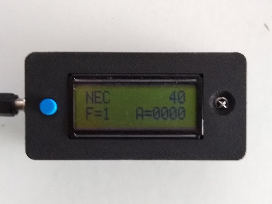
Going through boxes of junk that had been collected over a number of years, I came across dozens of infrared remote controls from various VCR's, TVs, LED strips etc. I thought I might keep some for say controlling a robotic car or other such projects. I needed a way of not only testing these remotes but also obtaining the command codes for each of their buttons.
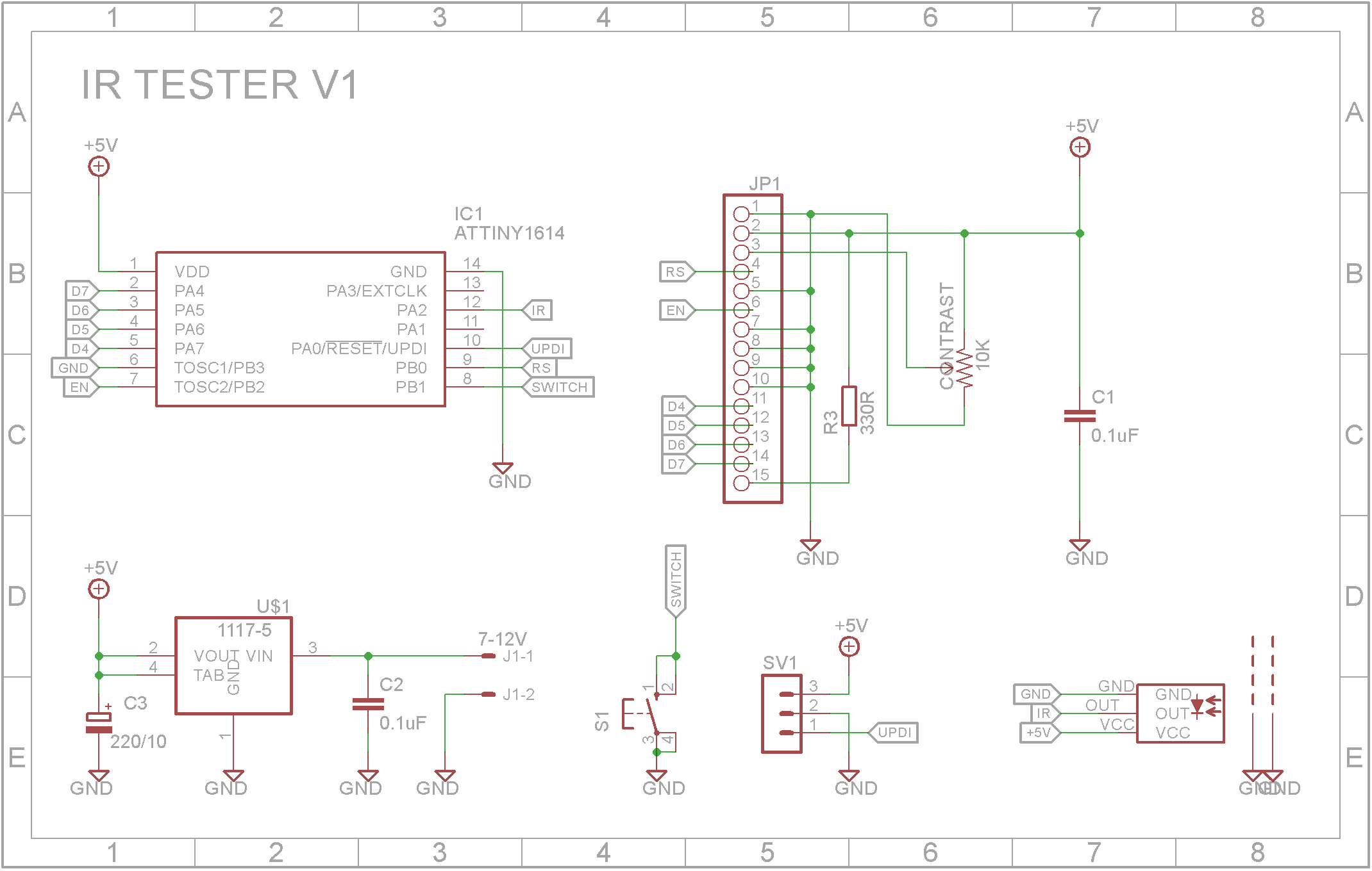
This build is a simple decoder and tester for infrared remote controls. It uses a cheap ATtiny1614 microprocessor, a IR receiver that was pulled off a DVD player and a 12 character by 2 line display that was purchased from some Rockby Electronics sale. (WH1202A)
Demonstration3D printingThe STL files are included. Either take these to a 3D print shop or if you have your own printer, run them through your slicing software. I used a 0.2mm layer height with no supports.
Drill out the PCB supports with a 2.5mm drill and create a thread with a 3mm tap.
Make sure the top fits snugly onto the bottom. You might need to do some filing if it is too tight.
The circuitThe circuit is very simple. It includes a 5V regulator allowing it to be powered by a 7-12V power brick. There is a tactile push switch that the software uses to show the raw unencoded data when pressed and the encoded data when released.
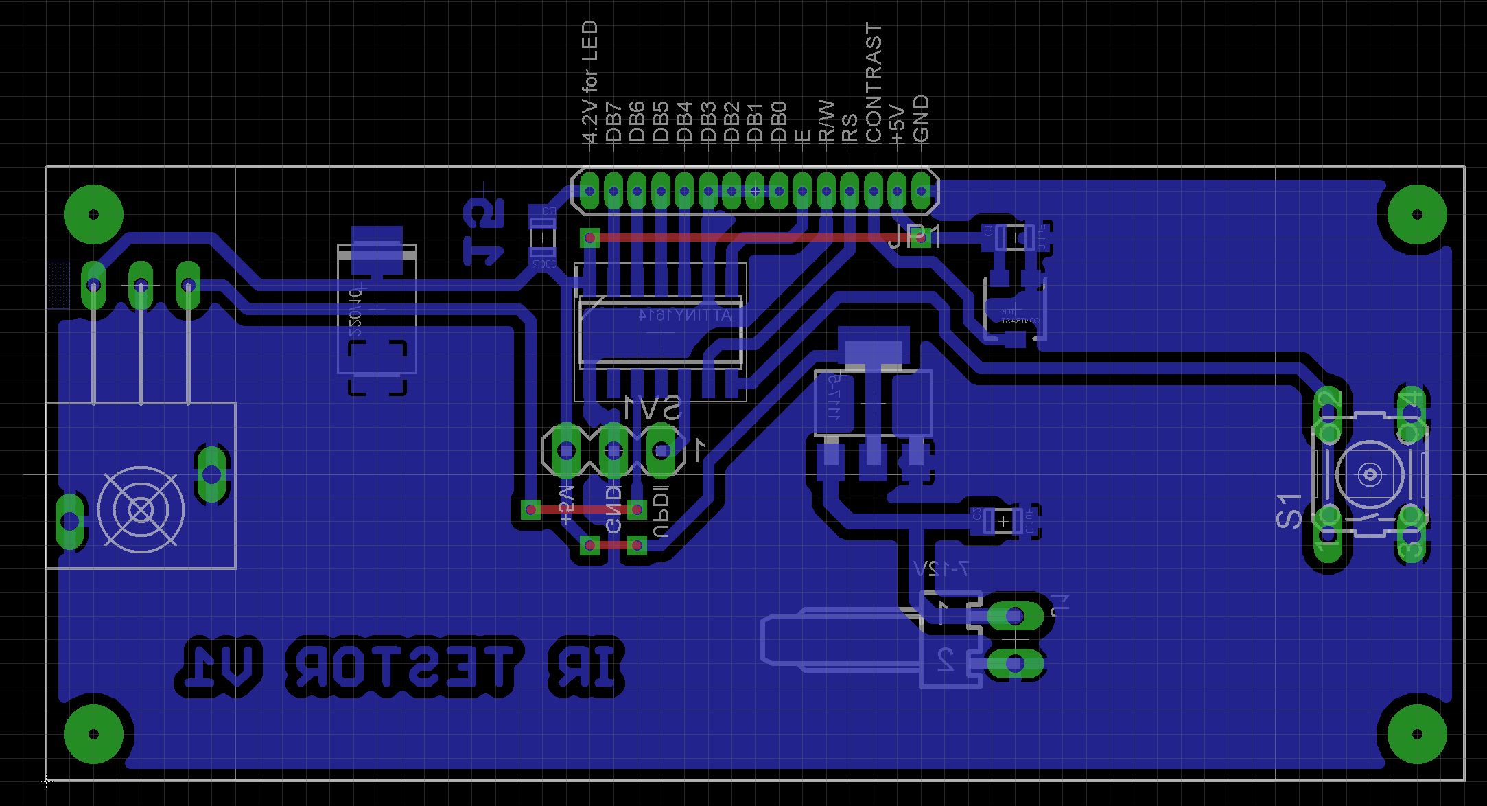
As the ATtiny1614 is only available in a SMD package, the PCB uses SMD packages through-out.
I have included the Eagle files in case you want to get the board commercially made or do as I did and make it yourself. I used the Toner method.
Start by adding the SMD components. I find it easier to use solder paste rather than use solder from a reel when soldering SMD components.
Add the links if your board is single sided.
Next add the headers. If you use headers on a single sided board, here is the method I use to add them.
Place header on PCB with longer pin side down, solder pins, push black plastic down towards the PCB.
I add a dab of red paint on the UPDI header's VCC pin and gray paint on the UPDI pin. This makes it easier to ensure the UPDI programmer is correctly connected.
To support the LCD display, add some packing to the top side of the board between the board and display. The WH1202A came with a 0.05in (1.27mm) male pin header. I purchased a 1.27mm female pin header from eBay which is mounted on the PCB allowing the LCD display to be removed.
Add the tactile push switch. Use super glue to glue on the button cap. Be carefully not to let the glue run down the shaft and into the switch.
Finally add the IR receiver.
Screw in the board using 4off 6mm M3 screws. Add the DC power socket to the bottom part of the case and connect it to the board. Make sure you get the polarity correct.
Unlike the earlier ATtiny series such as the ATtiny85, the ATtiny1614 uses the RESET pin to program the CPU. To program it you need a UPDI programmer. I made one using a Arduino Nano. You can find complete build instructions at Create Your Own UPDI Programmer. It also contains the instructions for adding the megaTinyCore boards to your IDE.
Once the board has been installed in the IDE, select it from the Tools menu.
Select the ATtiny1614 board in your IDE
Select the Chip to ATtiny1614 and set the clock speed to 16MHz and set the COM port to that which the Arduino Nano is connected to.
The Programmer needs to be set to jtag2updi (megaTinyCore).
Open the sketch and upload it to the ATtiny1614.
ConclusionThis tester does a great job on NEC and SONY remotes. Some remotes, while operational good, fail to be decoded because either they use a unknown protocol or the timing isn't quite correct. I have found this decoder very useful.


Comments