

Hardware components | ||||||
| × | 1 | ||||
 |
| × | 1 | |||
| × | 1 | ||||
| × | 1 | ||||
 |
| × | 1 | |||
| × | 1 | ||||
 |
| × | 1 | |||
 |
| × | 2 | |||
Software apps and online services | ||||||
 |
| |||||
Hand tools and fabrication machines | ||||||
 |
| |||||
 |
| |||||
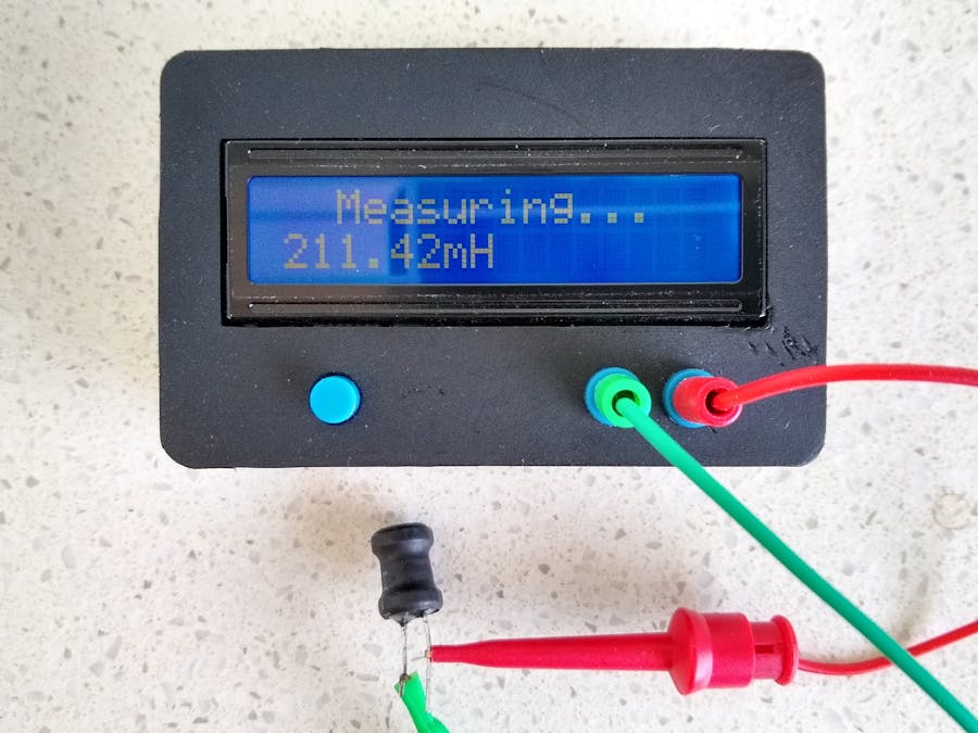
This project is a remake of an inductance meter by sagar saini. My variant has the following changes/additions:
- ATtiny1614 CPU replaces Arduino UNO
- LMV311 comparator replaces LM339 comparator
- Battery powered with deep sleep power off mode
- PCB and 3D printed case
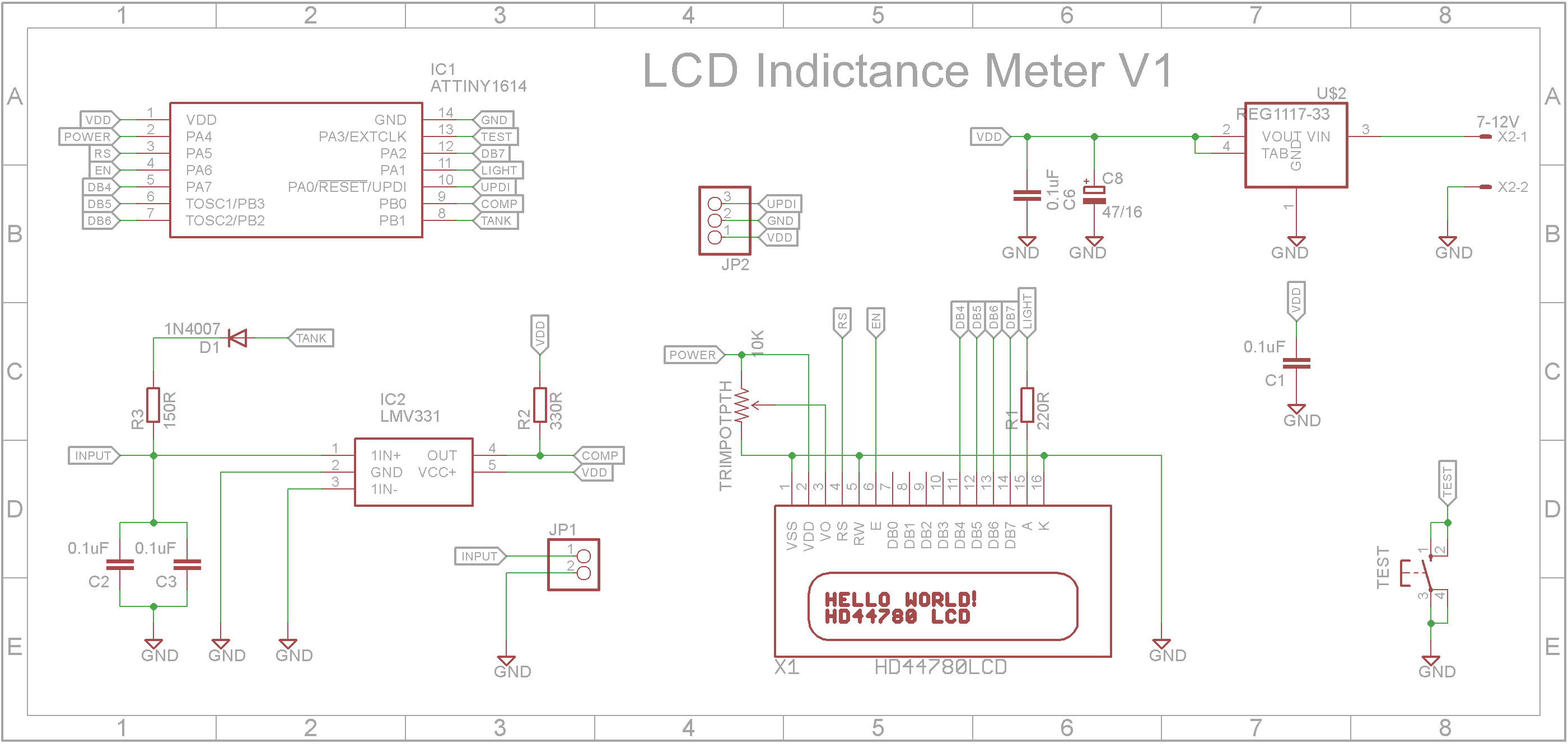
The updated circuit is designed around a ATtiny1614 microprocessor. This 14pin device has 16K Flash memory and 2K Static memory which is more than enough for this project. Unlike the ATmega328 microprocessor, the ATtiny1614 uses at lot less power while it is running and while it is in sleep mode thus providing good battery life.
The animated diagram shows the operation of a tuned circuit (LC or Tank circuit). The capacitor C stores energy in its electric field E and the inductor L stores energy in its magnetic field B (green). The animation shows the circuit at progressive points in the oscillation.
The frequency of oscillation is given by the formula:
By measuring the frequency and for a known capacitor, the inductor can be calculated.
Looking at the following code snippet:
digitalWrite(TANK, HIGH);
delay(5);
digitalWrite(TANK,LOW);
delayMicroseconds(100);
pulse = pulseIn(COMP,HIGH,5000);  //returns 0 if timeout
if (pulse > 0.1) //if a timeout did not occur and it took a reading:
{
  capacitance = 2.0E-7;  //Tank capacitor
  frequency = 1.0E6 / (2*pulse); //pulse is 1/2 the period. f = 1/period
  inductance = 1.0 / (capacitance*frequency*frequency*4.*3.14159*3.14159);
  inductance = inductance * 1E6;
  :
The TANK pin provides power to the tank circuit. This will charge the 0.2uF (2 x 0.1uF in parallel) capacitor. The pulseIn() function waits for the output of the comparator to go from LOW to HIGH, it then starts timing, then waits for the comparator to go LOW and stops timing. It returns the length of the pulse in microseconds or gives up and returns 0 if no complete pulse was received within the timeout (5000uS). This pulse length is half the period of the resonance frequency of the Tank circuit. Finally the inductance is calculated from the frequency and capacitance. The final line converts the inductance value in Henrys to micro-Henrys (uH).
Most 1602 LCD displays are designed to run at 5V. There are 3.3V versions available but they can be quite expensive. Most 5V boards can be converted to run from a 3.3V supply by added three components and changing a jumper.
1. Add a ICL7660 SOIC chip to U3
2. Add two 10uF 1206 capacitors to C1 and C2
3. Open J1 (remove solder) and close J3 (add solder bridge)
3D printingThe STL files are included. Either take these to a 3D print shop or if you have your own printer, run them through your slicing software. I used a 0.2mm layer height and no supports.
Drill out the three PCB mount holes with a 2.5mm drill and create a thread with a 3mm tap.
If the lid is lose, add blue painters tape around the rim of the bottom until the fit is tight.
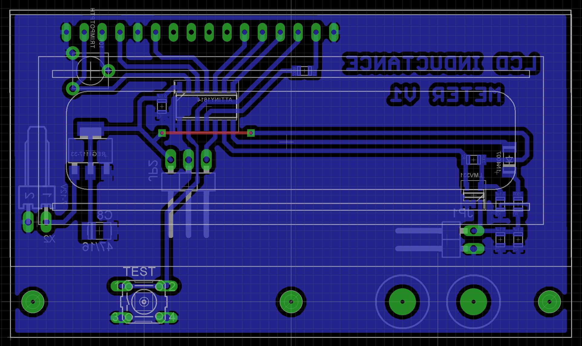
The PCBAs the ATtiny1614 microprocessor only comes as a Surface Mount Device (SMD), I decided to use SMD packages for most of the components in the build.
The Eagle files have been included should you wish to have the board commercially made or you can do as I did and make it yourself. I used the Toner method.
Assembly - Step 1Start by adding the SMD components. I find it easier to use solder paste rather than use solder from a reel when soldering SMD components.
Next add the link if you are using a single sided PCB
Solder the pin header for the UPDI programmer, banana sockets and the battery socket onto the copper side of the board. On the UPDI header, I usually dab some red and grey paint on the connector so I can easily identify the VCC and UPDI pins. (The unpainted one is GND).
Careful of shorts when soldering the 10K trimmer potentiometer that is used to set the contrast of the LCD.
When putting in the top side components, place some packing under the display. I used a couple of old pin headers with the pins removed. (See picture below)
Also super glue the button top on the switch shaft. Make sure the glue doesn't run down the shaft and into the switch.
Add the two 2mm banana sockets to the front panel. Fix the PCB assembly to the front panel using three 8mm M3 screws. Add a two pin female header to the wires from the banana sockets and plug it into the PCB.
The ATtiny1614 is part of the new breed of ATtiny microprocessors. Unlike the earlier series such as the ATtiny85, the new breed use the RESET pin to program the CPU. To program it you need a UPDI programmer. I made one using a Arduino Nano. You can find complete build instructions at Create Your Own UPDI Programmer. It also contains the instructions for adding the megaTinyCore boards to your IDE.
My home made UPDI programmer outputs 5V. Since the 1602 LCD display is now configured to run from 3.3V, you can't power the board with the UPDI programmer. Instead connect only the ground and UPDI wires (leave the 5V wire unconnected) and apply the power either from the 3.7V LIPO battery or an external power supply.
Connect the UPDI programmer
Once the board has been installed in the IDE, select it from the Tools menu.
Select board, chip (ATtiny1614), clock speed (8MHz) and the COM port that the Arduino Nano is connected to.
The Programmer needs to be set to jtag2updi (megaTinyCore).
Open the sketch and upload it to the ATtiny1614.
ConclusionThe inductance meter does a reasonable job at measuring inductances greater than 47uH. By changing the 0.2uF (the two 0.1uF in parallel in the tank circuit), you can adjust the range to suit your needs.


Comments