



Hardware components | ||||||
 |
| × | 1 | |||
| × | 1 | ||||
| × | 1 | ||||
| × | 1 | ||||
| × | 1 | ||||
| × | 1 | ||||
Hand tools and fabrication machines | ||||||
 |
| |||||
 |
| |||||
This project upgrades "Hand-Crank Flashlight Made From a Micro Servo – No Batteries Needed!" by CrazyScience. The upgrades are as follows:
- Diode added to provide protection to the LED when the crank is turned the wrong way.
- LED Driver to limit the current to the COB LED.
- Servo is screwed into the case rather than relying on glue.
- Servo handle is screwed on using a servo horn rather than relying on a pressure fit.
- Insert nuts added to the case so the screws aren't screwed directly into the plastic.
The servo needs to be modified to remove any lock that stops it from rotating the full 360 degrees. Also the electronics are removed so that the only connection is to the internal DC motor. This all requires the disassembly of the servo. See CrazyScience's description on how to modify the servo.
3D printingAll STL files required to print the hand torch have been modified. The updated STL files are attached.
All printing is done using a 0.2mm layer height. Use supports on "light+frame V2.stl".
Heat insert two M2.5 brass insert nuts where the servo is mounted. The servo is held in place with 6mm M2.5 screws. The servo handle uses the servo horn and screw that comes with the servo. Test that the handle rotates without any interference.
Heat insert four M2 brass insert nuts where the LED is mounted. The top section is held in place with 10mm M2 flat head (countersunk) screws.
ElectronicsThe electronics were mounted on a small piece of board cut from an Adafruit Perma-Proto 1/2 Sized Breadboard.
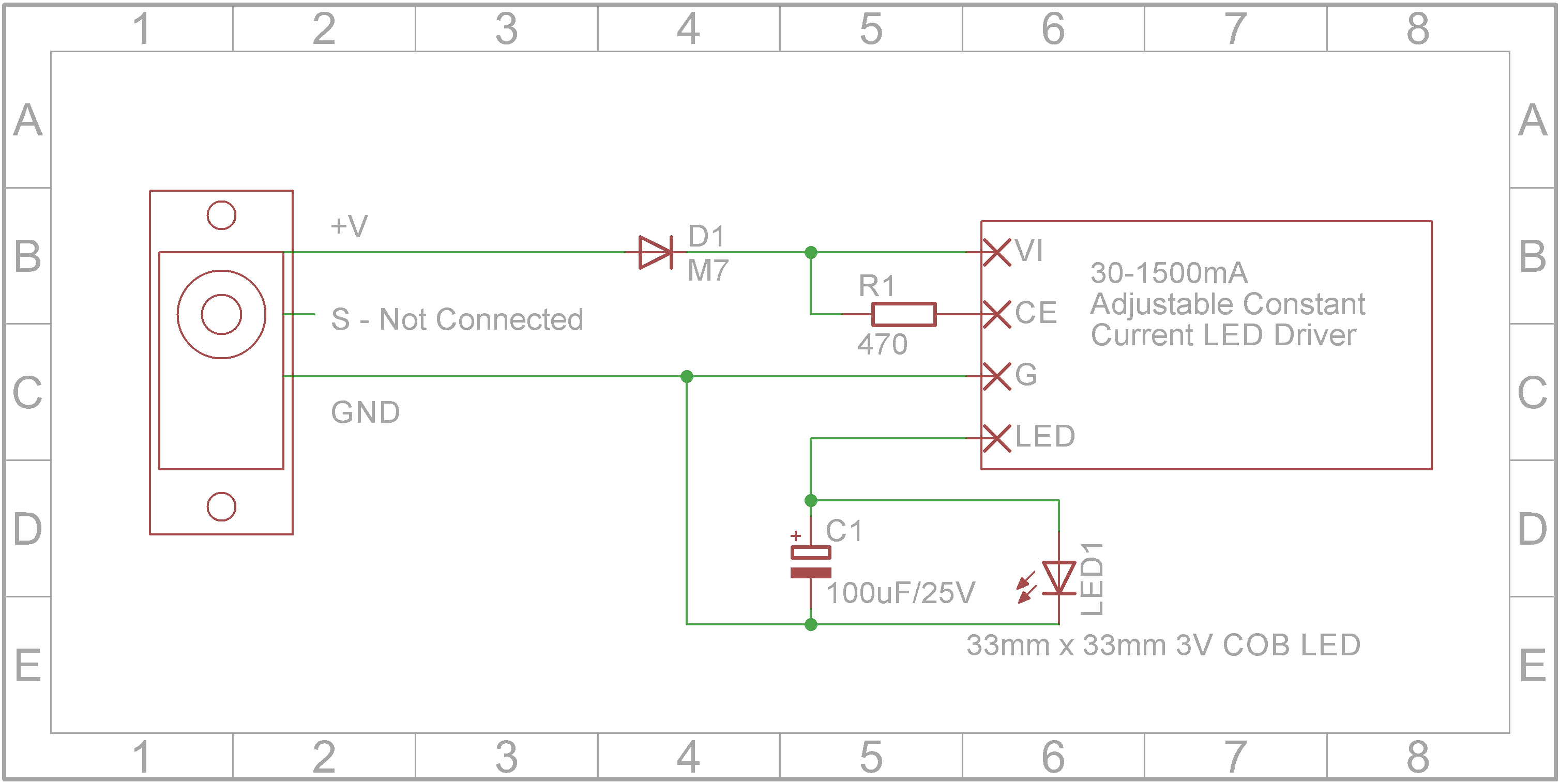
Start by soldering the M7 Diode, 470 Ohm 0805 resistor and 100uF 25V capacitor to the back side of the breadboard.
Add a 4 pin male header to the LED driver board and solder it to the top-side of the breadboard.
Solder the positive lead from the servo to the anode end of the diode (white wire) and solder the negative lead from the servo to the ground hole (grey wire).
Finally solder the red and black wires (positive and negative) to the top side of the breadboard. LED + terminal on the COB LED goes to the LED pin on the LED driver (positive) and the LED - terminal on the COB LED goes to the G pin on the LED driver (negative).
Test the LED lights up. Adjust the small trim-pot on the LED driver to set the maximum light intensity.
Finally add some heat shrink around the breadboard to it doesn't short on anything. You can also just enclose it in electrician tape.
Put the electronics in the case and put the COB LED into the top. Finally add the top plate and hold it in place with four M2 countersunk screws.
Your hand-crank torch is now complete.
Thank you CrazyScience for publishing an interesting and rewarding project. It was indeed an enjoyable build.


Comments