

Hardware components | ||||||
 |
| × | 1 | |||
| × | 1 | ||||
 |
| × | 1 | |||
 |
| × | 1 | |||
 |
| × | 1 | |||
 |
| × | 2 | |||
| × | 1 | ||||
| × | 1 | ||||
| × | 1 | ||||
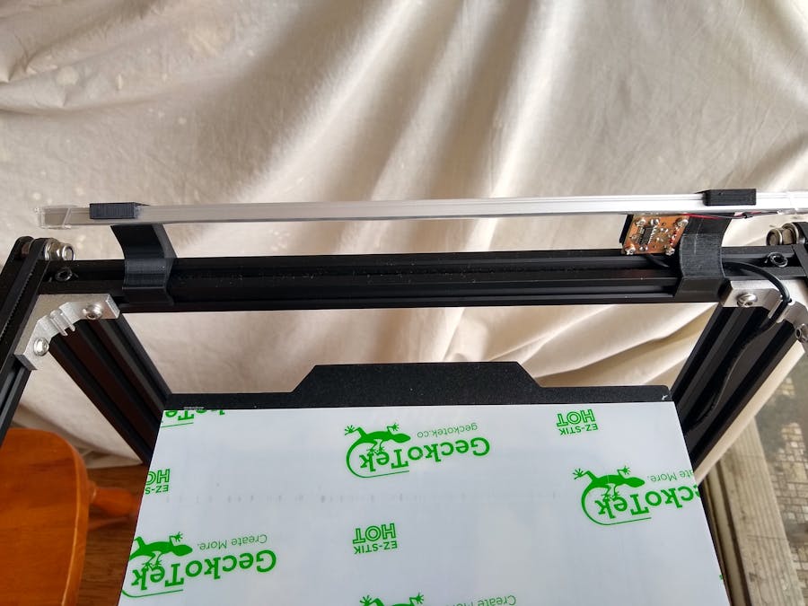
One of the "nice to have" things that is included with my Ultimaker 2+ 3D printer and not on my new Ender 5 3D printer is a lighting system that illuminates the build area. Looking around on Thingiverse, I found one designed by xqqqqme. Unfortunately the light bars used were a bit expensive and quite wide. I got a $4 one from eBay.
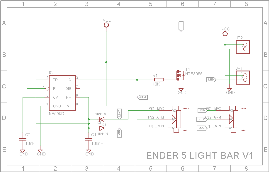
I didn't want a power switch so I decided to use the dimmer I designed for my Ray of Sunshine lamp. The dimmer circuit generates a 1KHz square wave with the slider potentiometer able to vary the "on" time from fully off to fully on.
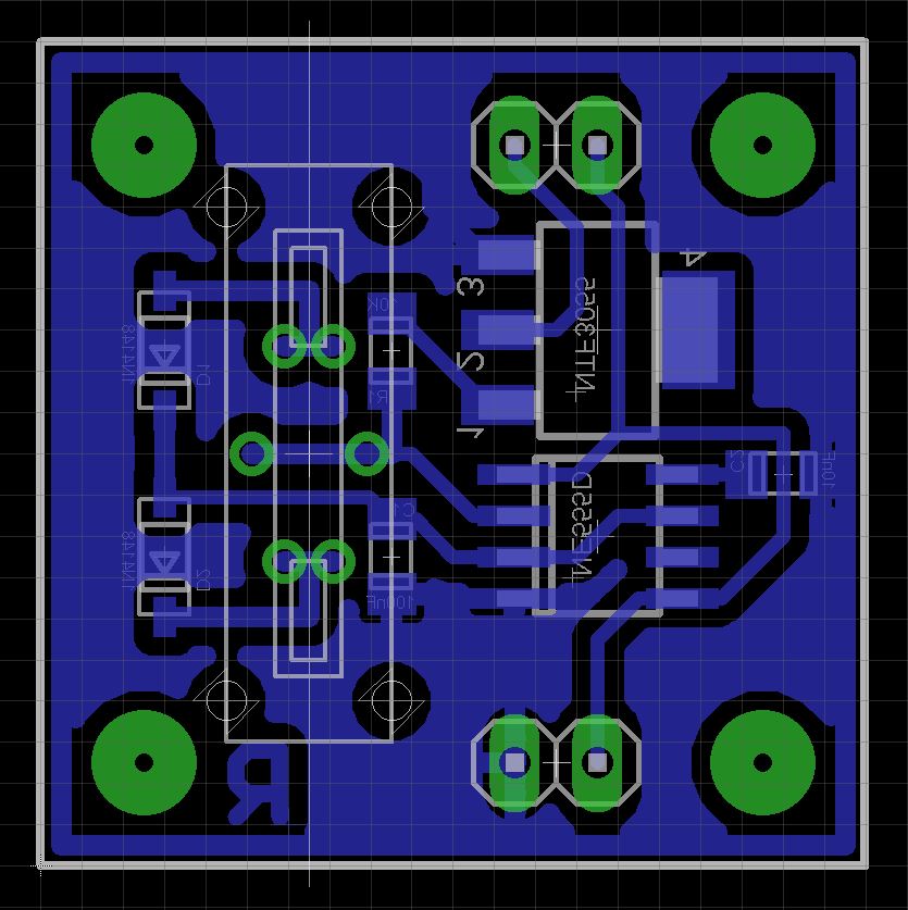
I had a number of 18mm slider pots that I got from Rockby Electronics. This allowed the dimmer circuit to fit on a 1 inch square printed circuit board.
3D PrintingOrientate the "Light Holder V1.stl" 90 degrees around the Y axis and print without supports.
Print the "Light Holder + PCB V1.stl" with supports. Drill out the PCB mount holes with a 2.5mm drill and create a thread with a 3mm tap.
PCBThe Eagle files have been included should you wish to have the PCB commercially made or you can make it yourself. I made mine using the Toner method. Start my soldering the SMD components - The schematic shows a 10K potentiometer and C1 as 100nF capacitor. However if like me, you used a 2K potentiometer, change C1 to a 470nF capacitor.
Next solder on the slider potentiometer. Remove the ends of the LED bar. Mine were just held on by a bit of hot glue. Unsolder the wires off the end of the LED strip and solder them to the JP2 connection. Measure and cut two wires to run from the board to the light bar. Solder them in place. You can now screw the PCB to its mounts. Use M3 x 6mm screws.
Test that everything works. Once you are happy with it, super glue the LED bar to the mounts. Make sure you measure where to glue them first. They need to be as wide as possible but also clear the corner brackets on the frame. Leave the glue to cure for 24 hours.
Unbolt the screw on each corner bracket and the two bolts holding the front frame piece to the uprights. You should be able to carefully take out the top bar. Slide the LED bar onto the top frame piece and screw it back in place.
I routed the cable down the closest vertical post.
You can either use a 5V USB power adapter or you can do as I did and hard wire it into the Ender 5 electronics.
Firstly I cut the cord at the switch. I also drilled a 6mm hole into the Ender 5 electronics enclosure and inserted a suitable grommet. This allowed me to feed the cable into the electronics enclosure.
There doesn't appear to be any freely accessible 5V supply available so I took a small 3A DC-DC Buck Step-Down regulator and set its output to 5V. I connected the regulator input to the spare screw terminals on the power supply and soldered the wires to the LED Bar to the regulator output.
Once tested, the whole regulator was covered with a piece of heatshink.
ConclusionThe light makes it so much easier to monitor the print especially at night when shadows are cast on the build area.


Comments