


Hardware components | ||||||
| × | 1 | ||||
 |
| × | 3 | |||
| × | 1 | ||||
| × | 1 | ||||
Hand tools and fabrication machines | ||||||
 |
| |||||
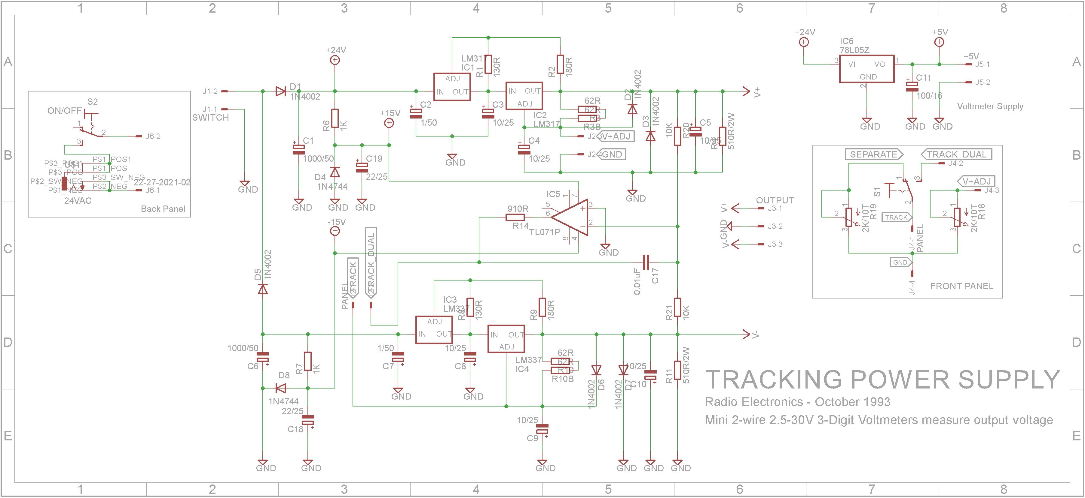
When experimenting with OP-AMP circuits, a dual power supply providing equal positive and negative supply lines is extremely useful. This project is based on a dual tracking adjustable power supply by John F. Keidel that was published in Electronics Now in October 1993 (Article attached).
My version of this power supply makes the following changes:
- Dual tracking mode always enabled (The original circuit allows you to have dual tracking of both positive and negative outputs as well as to adjust them individually).
- Removed the separate 5V output as I didn't need it.
- Replaced the 15V analog panel meter with a 0-100V digital meter. I added an extra regulator to provide power to the digital meter. The digital meter is hard-wired to measure the positive output only.
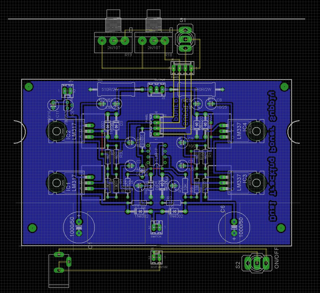
- Designed a new PCB to fit into a 140x110x35 instrument case purchased from Jaycar Electronics.
Sourcing 124 ohm resistors was problematic so I ended up using two 62 ohm resistors in series.
The 5V output circuitry was removed and replaced with a 74L05 regulator to power the digital voltmeter.
While the schematic shows wiring for dual tracking and separate adjustment of the individual positive and negative outputs, R19 (Negative 10K multi-turn Pot) and S1 (Separate, Track Dual switch) was removed in the final build. J4-1 and J4-2 connections were permanently joined so the power supply only operated in Track Dual mode.
What isn't shown on the schematic is a DPST rocker switch that sits between the OUTPUT connector on the PCB and the OUTPUT banana sockets on the front panel. The switch switches on/off the positive and negative outputs.
Parts ListFollow the layout below to assemble the PCB.
The 1000uF 50V electrolytic capacitors are placed on their sides as shown below. Use heatsinks on the LM317 and LM337 regulators.
Wire up the front panel. Note that the DPST switch sits between the OUTPUT connector on the PCB and the OUTPUT banana sockets on the front panel. The switch switches on/off the positive and negative outputs.
Also note that the 4 pin KF2510 connector has the switch terminals shorted (blue wire) and the green and yellow wires go to the 2k Multi-turn Potentiometer.
If you wish, you can 3D print the attached "Dual legs.3mf" file. Assembly the feet and glue them onto the bottom of the case 5mm from the front and 5mm from each side. Make sure they are orientated correctly before you glue them into place.
You will need a 240VAC to 24VAC power brick to obtain the maximum voltage output of +/-30V. I used a 240VAC to 16VAC power brick and obtained a maximum output of +/-20V output which was more than adequate for my needs.
The regulators are rated at 1.5 Amps so don't try and exceed this.
ConclusionThis has proved to be a useful project when it comes to developing and experimenting with OP-AMPs and Active filters.

Comments