



Hardware components | ||||||
| × | 1 | ||||
| × | 1 | ||||
| × | 1 | ||||
| × | 1 | ||||
| × | 1 | ||||
Hand tools and fabrication machines | ||||||
 |
| |||||
 |
| |||||
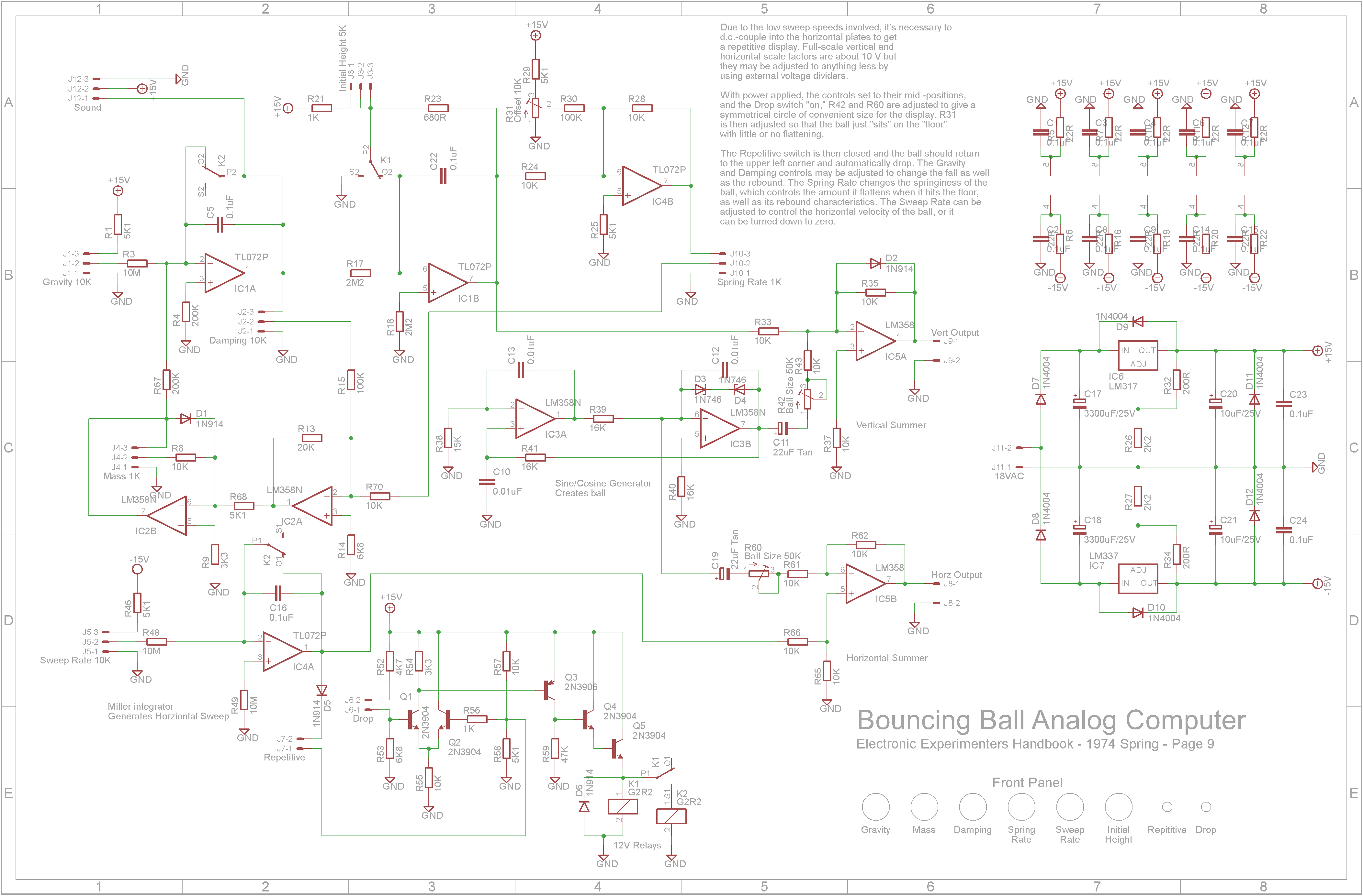
Back in 1974, Electronic Experimenter's Handbook published a Bouncing Ball Analog Computer by Terry L. Mayhugh. It emulated a ball falling from a height and bouncing along the ground. The path was displayed on an oscilloscope.
Although I originally built this project back in 2017, my 3D printer at the time had a small build area so my first build had a case made from wood.
This project replaces the old wooden case with a 3D printed instrument case.
The Analog Computer(reprinted from Electronic Experimenter's Handbook)
An analog computer may be likened to a slide rule. Both provide instantaneous answers on a continuous scale without absolute accuracy. (In contrast, digital computers are essentially fast arithmetic machines that solve one problem at a time with great accuracy.) Analog computers can simulate a variety of factors by substituting electrical models.
The computer described in this project, for example, can be programmed to solve an interesting problem:
Given the initial height of a ball of known mass above a hard surface, the force of gravity, the viscosity of the medium, and the spring constant of the ball, how does the ball behave when it is dropped?
The computer "paints" a ball on the screen of an oscilloscope and, when given the Drop command, computes and displays continuously the path of the ball as it falls, compresses at the hard surface, rebounds, and finally settles on the floor.
The machine quickly does the calculations for a continuous display which would take an engineer days to complete by hand and plot. The operator controls the parameters Gravity, Mass, Damping, Spring Constant, as well as the horizontal velocity across the screen. A repetitive mode is also provided for a repeating display.
Although analog computers cannot give the 15 decimal place accuracy of their digital cousins, they are better suited for solving "real time" problems that would otherwise require a knowledge of differential calculus.
More precise quantitative results than possible with the project's computer would require an expensive version of it with controlled offset errors, calibrated potentiometers, etc. Nonetheless, the unit described gives a fair approximation of what happens with a "bouncing ball."
3D printingThe STL files for the case are attached. All printing is done using a 0.2mm layer height. You may need to orientate the parts on the build plate before slicing.
When printing "Bouncing Ball Computer V1 - Text.stl", switch to a filament of a contrasting color at the start of layer 4.
Print "Bouncing Ball Computer V1 - Front.stl" with supports. After printing, remove the supports and add the potentiometers to their respective holes. Do not use washers as the nuts need sit below or flush with the front.
Place double-sided tape on the back of "Bouncing Ball Computer V1 - Text.stl" and stick it to the front of "Bouncing Ball Computer V1 - Front.stl".
Finally add the toggle switches.
Add 4mm diameter by 3mm high M3 brass inserts into the holes on the tabs for the bottom and top clam-shells.
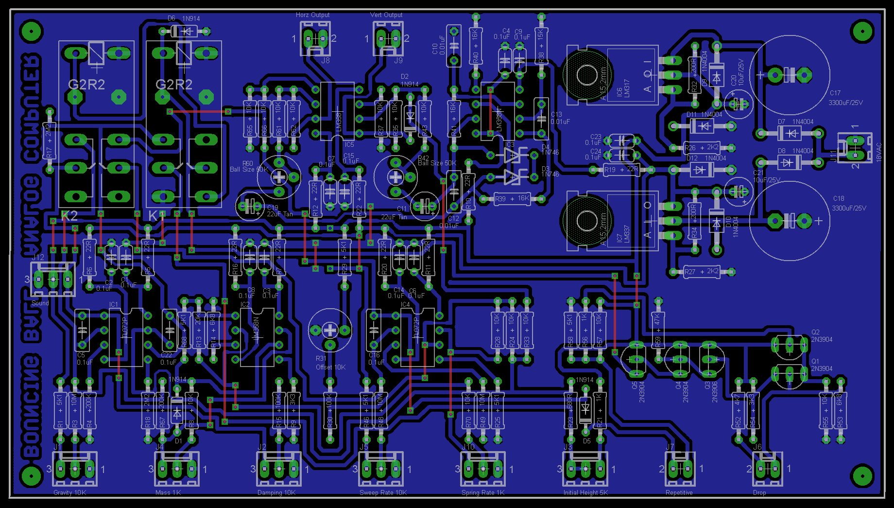
AssemblyI have included the Eagle files in case you want to get the board commercially made or do as I did and make it yourself. I used the Toner method.
Add the links if your board is single-sided.
Add the diodes and resistors.
Add the IC sockets or you can just solder on the ICs.
Add the capacitors, trimpots, relays and transistors.
Add the pin-headers and KF2510 connectors.
Screw the PCB to the front panel using 4 x M3 4mm screws.
Wire up the two BNC connectors on the back panel.
Wire up the potentiometers and switches on the front panel.
Screw on top clam-shell using 4 x M3 6mm black hex screws.
ConclusionWhile this project was pretty remarkable back in 1974, it has little practical use now other than the enjoyment of building it. Digital computers can demonstrate and display the physics of a bouncing ball more precisely and cheaper than building a dedicated analog computer.
One of the things that has changed over time is the oscilloscope. The old heavy analog oscilloscopes have been replaced with digital oscilloscopes in many workshops both small and large. I tried this computer on my Hantek DS02D10 digital oscilloscope and it looks crap on its TFT LCD screen. It definitely looks better on an analog oscilloscope with its phosphorous display.
Discrete electronics without microprocessors is still fun. It's a pity in some-ways that it is a dying art but if you are interested in looking at old electronic magazines, the best source that I have found is https://worldradiohistory.com/



Comments