


Hardware components | ||||||
| × | 1 | ||||
| × | 1 | ||||
| × | 1 | ||||
| × | 1 | ||||
| × | 1 | ||||
| × | 1 | ||||
| × | 1 | ||||
| × | 1 | ||||
Hand tools and fabrication machines | ||||||
 |
| |||||
 |
| |||||
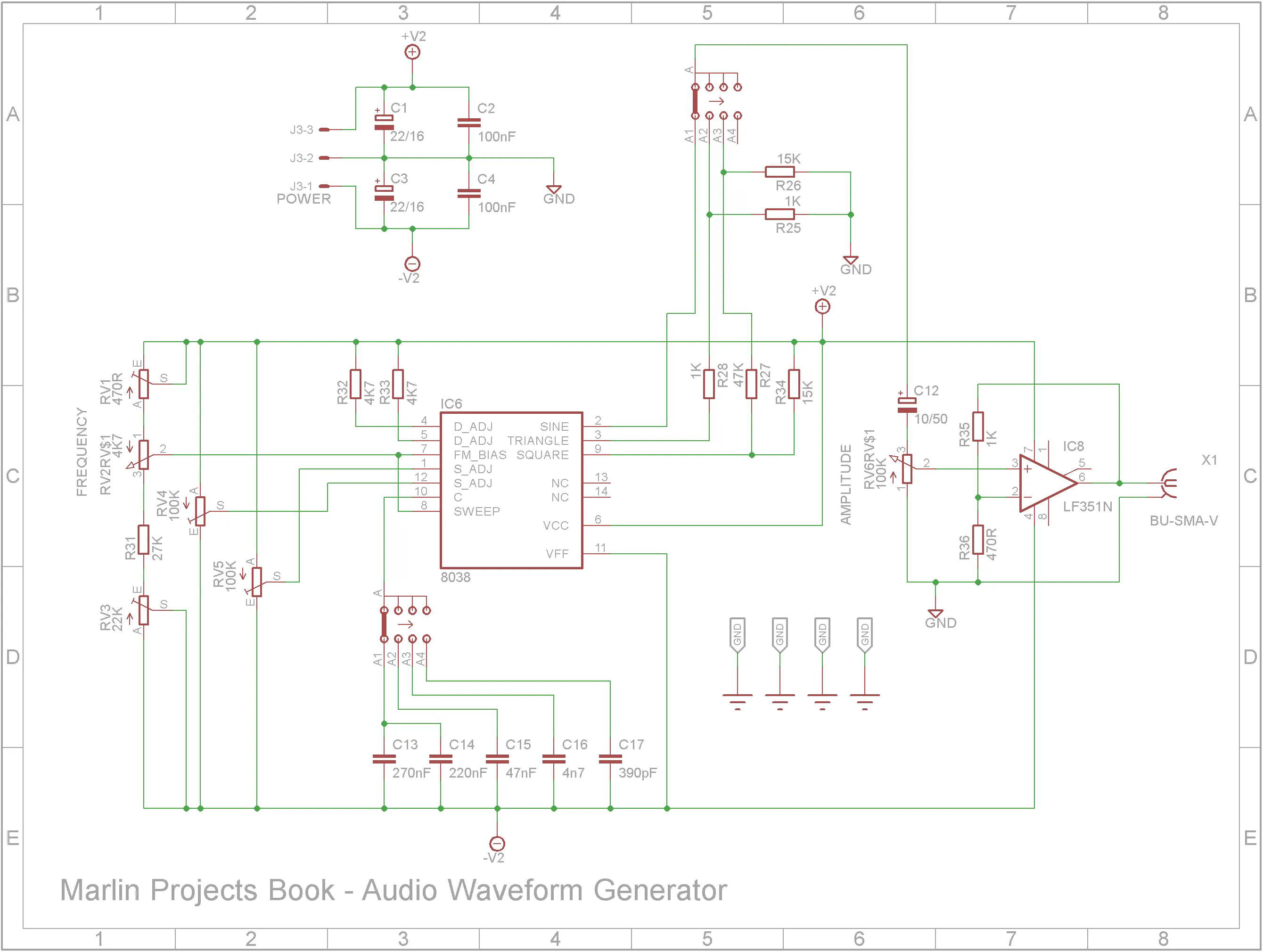
Around 7 years ago, I built a Audio Waveform Generator that appeared in Maplin Projects Book - 48 (1994). It produced good quality Sine, Triangle and Square waveforms. It featured push-button switching to switch between the different waveforms and the frequency ranges. This was certainly a novel alternative to rotary switches back in 1994. However it does take more room on the front panel and also on the PCB because of the extra circuitry required.
You can find my first build of this project at Thingiverse.
The quality of the waveforms outputted from this generator is very good as you can see below.
I decided to upgrade this project by reducing it's footprint, making it more suited to a sit on workbench shelf and to have it powered by the mains rather than 9V batteries.
Although the push-button switch system was an interesting replacement for rotary switches, it took a lot of space both in terms of front panel and PCB layout. So this build replaces the push buttons and LEDs with two 16mm rotary switches.
3D printingThe STL files for this project are attached. All printing is done using a 0.2mm layer height. You may need to orientate some of the files on the build plate before printing.
When printing "Audio Waveform Generator V2 - Text.stl", change to a contrasting filament color at the start of layer 4. After printing, add double sided tape to the back of the print and stick it to "Audio Waveform Generator V2 - Front.stl".
When printing "Audio Waveform Generator V2 - Knobs.stl", change to a contrasting filament color at the start of layer 61.
Add M3 3x4.2 brass insert nuts to the tabs on "Audio Waveform Generator V2 - Bottom.stl" and "Audio Waveform Generator V2 - Top.stl".
Add M3 3x4.2 brass insert nuts to the power supply studs on "Audio Waveform Generator V2 - Bottom.stl"
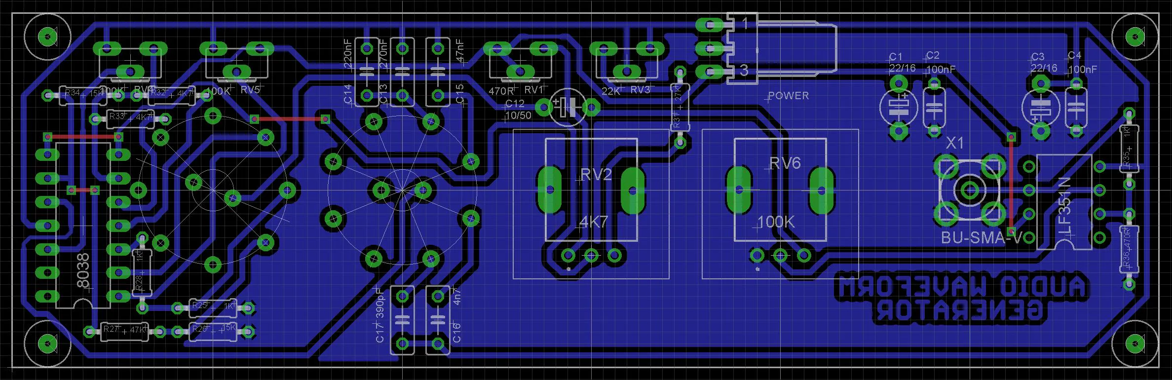
Add the links if your board is single-sided.
Add the resistors next followed by the 8038 and LF351 ICs.
Add the capacitors and trimpots.
Add the SR16 rotary switches, RV09 potentiometers and SMA socket.
Finally add a 3-pin KF2510 to the copper-side of the PCB.
Screw the PCB to the front panel using 4x M2 4mm screws.
Add the rocker switch to the front panel
Screw in the SM-FLA17A 17W positive and negative two switching power supply module using 4 x M3 4mm screws.
Wire up modules and power components. I purchased a 3.96mm JST kit for the connections to the SM-FLA17A power module. The switch and AC-03 power socket use 4.8mm spade connectors. The front PCB power connector uses a 2.54mm JST connector.
Screw on top clam-shell using 4 x M3 6mm black hex screws.
I am really pleased how this upgrade turned out. It looks professional when sitting on a workbench shelf. For audio work, it is more than adequate.


Comments