


Hardware components | ||||||
 |
| × | 1 | |||
 |
| × | 1 | |||
| × | 1 | ||||
 |
| × | 1 | |||
 |
| × | 1 | |||
| × | 1 | ||||
| × | 1 | ||||
| × | 1 | ||||
Hand tools and fabrication machines | ||||||
 |
| |||||
 |
| |||||
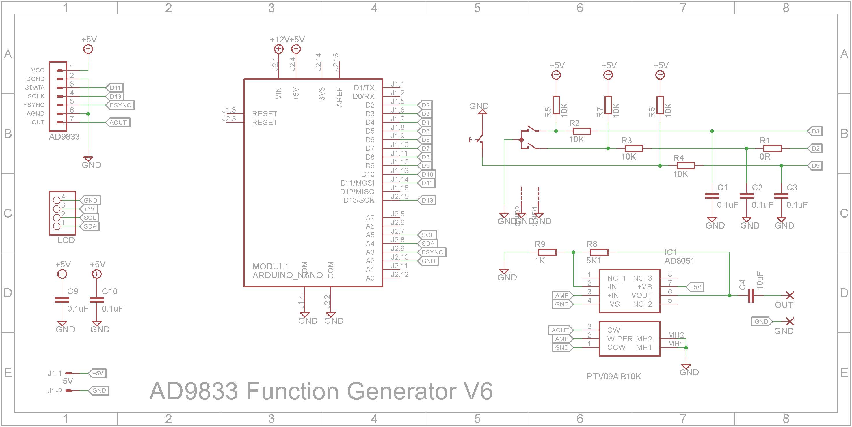
This is my third AD9833 function generator that I have built over the years.
I liked the case design of the first version and the portability of the second version. This new version appears similar to the first version in appearance. Inside it contains a UPS module so it can run from 18650 3.7V battery or be powered by a USB-C power supply. While being externally powered it will recharge the battery even when the unit is switched off.
The module contains a boost circuit to boost the 3.7V battery or 5V external supply to 12V.
The output stage has been enhanced with a higher frequency op-amp.
3D Printing"Box - Back V6.stl" - 0.2mm layer height, 20% infill, Rotate 90 degrees about the Y axis, no supports
"Box - Bot V5.stl" - 0.2mm layer height, 20% infill, Rotate 180 degrees about the Y axis, no supports
"Box - Front V6.stl" - 0.2mm layer height, 20% infill, Rotate 90 degrees about the Y axis (text facing up), no supports, change to contrasting filament a start of layer 11.
"Box - Knobs V5.stl" - 0.1mm layer height, 50% infill, no supports, change to contrasting filament a start of layer 81.
"Box - Top V5.stl" - 0.2mm layer height, 20% infill, no supports.
When printing "Box - Text V6.stl", change to a contrasting filament color at the start of layer 4. After printing, add double sided tape to the back of the print and stick it to "Box - Front V6.stl".
Drill out the four PCB supports on "Box - Top V5.stl" with a 2.5mm drill and create a thread with a 3mm tap.
The lugs that hold the shells together are a bit fragile. I glued on washers before I drilled the holes with a 2.5mm drill and created a thread with a 3mm tap. Drill out the holes that the screws go through with a 3mm drill.
After printing "Box - Back V6.stl", add four 3.5mm OD x 4mm high M2.5 inserts into the mount holes using hot iron. The temperature of the iron should be set to less than 200C.
Screw on the USB-C socket using two M2 8mm screws each with a washer, spring washer and nut. Solder the positive and negative leads from the USB-C socket to the UPS pads as shown below.
Insert the power switch in the hole provided and connect the switch to the two holes in the middle of the UPS module.
Finally add a KF2510 2-pin female connector to a pair of wires and solder them onto the output connections of the UPS module.
Screw the UPS module onto the back panel using four M2.5 x 4mm screws.
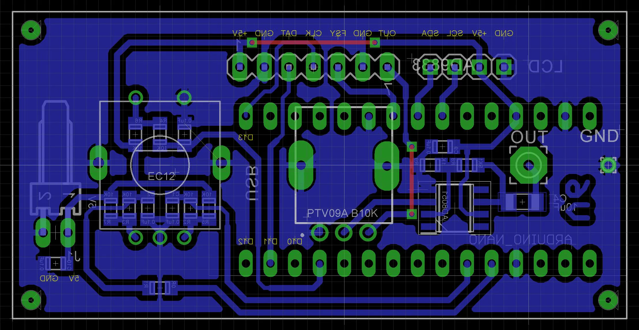
I have included the Eagle files in case you want to get the board commercially made or do as I did and make it yourself. I used the Toner method.
Start by adding the SMD components. I find it easier to use solder paste rather than use solder from a reel when soldering SMD components.
I used my SMD Reflow Hot Plate to reflow the solder paste.
Add the links if your board is single-sided.
On the copper side of the PCB:
- Add a 4 pin header for the cable to the LCD 1602 display.
- Add two 15 pin headers to mount the Arduino Nano.
- Add a KF2510 2 pin right angle connector for the power
On the component side of the PCB
- Add the rotary encoder
- Add the 10k RV09 Potentiometer
- Add the SMA socket as shown below. Note the wire from the eye connector to the PCB board.
Add a 7-pin right angle pin header to the AD9833 module
Solder the module on the copper side of the PCB
Add two 15 pin female headers to the Arduino Nano module.
Screw the PCB and LCD 1602 display module to the front panel using eight M2 4mm screws.
Add a four pin lead from the PCB to the LCD 1602 display module. Note that the SDA and SCL wires are swapped at one end.
Connect the USB cable to the Arduino Nano and upload the software via the Arduino IDE.
Final AssemblyIf you wish, you can 3D print the attached "Dual legs.3mf" file. Assembly the feet and glue them onto the bottom of the case 5mm from the front and 5mm from each side. Make sure they are orientated correctly before you glue them into place.
Join the clamshells using four 6mm M3 screws.
Overall the final appearance looks nice on the benchtop. The portability just makes the unit more than just another workshop shelf unit.


Comments