

Hardware components | ||||||
 |
| × | 1 | |||
| × | 1 | ||||
| × | 1 | ||||
| × | 1 | ||||
 |
| × | 1 | |||
| × | 1 | ||||
Software apps and online services | ||||||
| ||||||
| ||||||
| ||||||
| ||||||
| ||||||
Hand tools and fabrication machines | ||||||
 |
| |||||
When there is candy within reach, many people tend to grab and eat multiple pieces without thinking about if they really want to be eating them. To make it slightly harder for someone to eat a piece of candy without thinking about if they really want it, I created a candy game box.
How it WorksThere are 4 LED buttons of different colors on the top of the box. When the green button is pushed, the game starts. For the initial level, a random pattern of 7 LED buttons light up. The user then repeats the pattern by pressing the buttons in order. If the user is correct, the servo motor spins and releases a piece of candy, in this case a Jolly Rancher, from the box. For the next 20 minutes the difficulty level is increased. For the first five minutes, 15 LEDs light up. For the next 5 minutes, 13 LEDs light up. For the following 5 minutes, 11 LEDs light up. For the last five minutes, 9 LEDs light up. The difficulty then returns to the default state. This is to make it harder for someone to continually win the game and receive multiple pieces of candy in a short time frame. The other part of this is if the user incorrectly repeats the pattern the buzzer sounds and they are locked out of playing for the next 20 minutes. Below are videos showing the functions of the final candy game box.
There were three major parts to this project. The first was the coding, the second was the wiring, and the third was designing and building the box and its mechanisms. All the code used and more information about it can be found following this link: Github Files. The final game code is also farther down this page.
WiringFor wiring, I first did the buttons and their LEDs so the main part of the code could be created. The picture below shows the wiring of only the LED buttons. The transistor needed to be used for the red and yellow LEDs. For these LEDs, the GPIO connected to the transistor B port. The transistor C port connected to LED-. LED+ was connected to power, Vout. The transistor ground connected to GND. For the green and blue LEDs, the GPIO port connected directly to LED+, while LED- connected to GND. For all the buttons, a 1kohm pull up resistor was used. The GPIO port was connected to the pull up resistor and the button. The other side of the pull up resistor connected to power, +3.3V while the button connected to GND. For testing the buttons, I found it easiest to make a stand out of an empty tissue box. This held the buttons so they could be pressed and the LEDs could easily be seen.
To secure the connections on the LED buttons, an additional wire was added to each prong. This wire was soldered to the LED button prong on one side, and on the other side was soldered to the respective jumper cable. The positive wires are color coded for their respective LED or button. The ground wires are neutral.
The next part for the wiring was attaching the servomotor, display, and buzzer. For the buzzer, the positive end connected with a PWM port while the negative end connected with GND. For the servomotor the ground wire connected to GND, the VCC wire connected to Vout, and the PWM wire connected to PWM0. For the display the power comes from +3.3V. The display's + pin is connected to power and the - pin is connected to GND. SCL connects to pin C, while SDA connects to pin D. SCL and SDA also connect to 1kohm pull up resistors that go to power. The final wiring is in the pictures below. The wire coloring does not correspond with the color coding in the fritzing diagram.
On the fritzing diagram, the wires are color coded to make it easier to understand. The red wires are used to work the red LED button. The yellow wires are used to work the yellow LED button. The green wires are used to work the green LED button. The blue wires are used to work the blue LED button. The yellow, red, and black wires on the servo are not connected to the LED buttons. The gray wires are for ground and power connections. The purple wires are for the speaker. The orange wires are for the display.
The last part was making the box and the mechanism to release the candy. I started with making a mechanism that worked. The servomotor came with a wheel that could attach to it. I cut a square wood dowel into 8 pieces. I then superglued these pieces evenly apart on the wheel. This allows the candy to sit between the two pieces and roll out when the motor turns. The picture of this is below.
After confirming that the motor would move the candy with some tests, I started creating the CAD files for the box. All the files are farther down this page. The main challenge with this was creating the correct size and spacing for the tabs. After I felt satisfied with the CAD files, I converted them to Adobe Illustrator and laser cut them. The laser can be seen cutting the wood in the picture below.
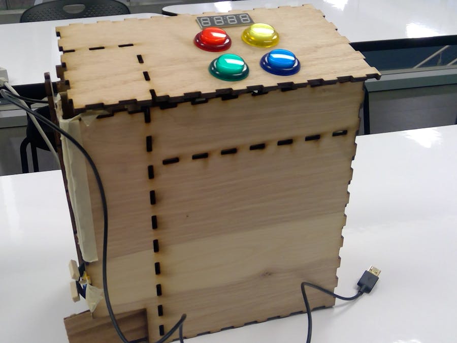
After laser cutting the box, it was time to put it together. The box has some issues with the fit between pieces, so it is not fully connected currently. The pieces are all being held together, but not all of them are connected with their tab joints. The overall shape and size can be seen in the photo below. The box has three compartments: candy dispensing area, circuit holder, and storage.
The candy dispensing area had a built in hole in the front plate for the candy to come out of, but it is currently too small. The mechanism was moved to the side of the same compartment. The side the candy is coming out of now is meant to have a removable wood piece for fixing and loading. A rectangular chute holds the Jolly Ranchers, while the fall onto the spinning wheel. The chute is just slightly bigger than the candy to prevent jams from multiple pieces trying to go into the area.
The next section is the storage on back. When making the CAD files, I realized there would be a lot of wasted space in the box, so I made it storage. This allows refills of candy to be kept with the box. Having the opening on the back, keeps the storage unit out of the way and less accessible. The two quarter circle holes are used for moving the door. The hinge was attached to keep the door piece attached to the back.
The final section houses the Pocket Beagle and all the wiring. This section is directly underneath the top lid, since that is where the LED buttons and display are located. The buzzer is not on the top piece, since it can be heard through the wood and does not need to be seen. The platform could be slightly lower to give more room for all the jumper cables. The inside of this section with everything present is below.
- Work on getting the box to fit together completely: could include altering some pieces or creating new ones
- Add holes for wires that cross sections (servomotor wires and power cord)
- Make a bigger dispensing hole for the candy
- Make a better and more stable dispensing mechanism once the box is put together correctly
- Implement the display by adding comments based on the situation such as win, lose, and lock
- The CAD files can be adjusted for various purposes such to make the box fit together better, change in size, change in section locations, and adding additional holes and features. The current tabs were based on a wood with thickness 0.12in, they will definitely need to be changed for any material with a different thickness. I think they wood I ended up using was slightly thicker than 0.12in so that is affecting the fit. The circuit platform is currently two inches below the top lid. This should be lower to better fit the wires.
- The settings for pattern lengths, times, servo speed, and buzzer sound can be easily changed within the code.
- The project could be changed to release other types of candy. The release mechanism can also be altered as desired. The CAD files would likely need adjusting for this.


Comments