

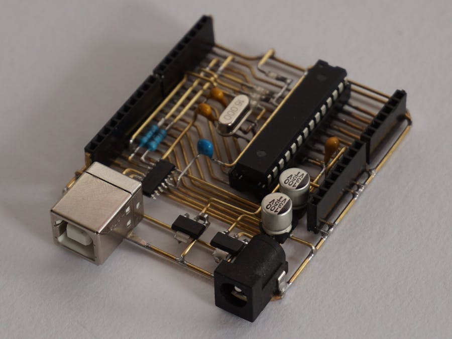
Yeah, I've really done that. It was hard, took me several days but I made it. In the end, it was an excellent experience and the most amazing thing is that Freeduino actually works. And I would like to share my experience with you.
What is Freeduino? It's famous Arduino UNO board made without any circuit board. It uses a technique called free-form to interconnect components by wires instead of a board. And it looks beautiful!
Why I made it? I often have a hard time explaining what free-form electronics is and how it looks like. Freeduino is an excellent example of free-form electronics art easily comparable to a well-known device - Arduino UNO.
Check out my simple brass LED jewelry for the basics of brass soldering, required tools, and materials.
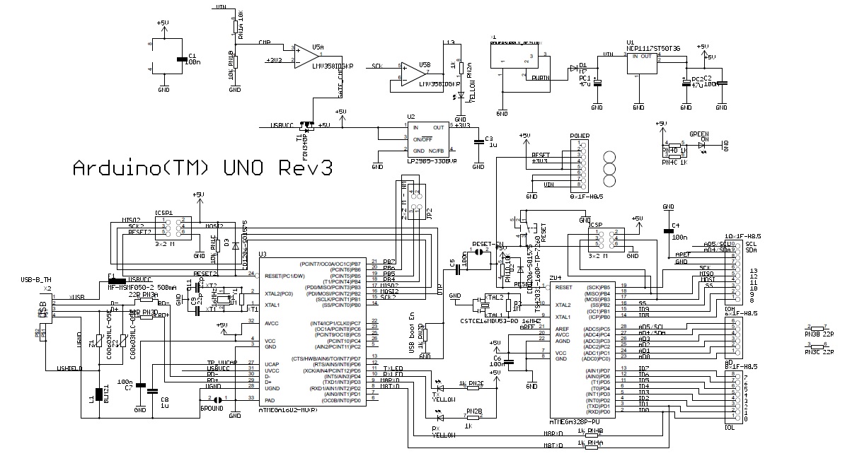
Understanding Arduino UNO circuitPrior to actually start soldering it, I needed to know what exactly is on board of Arduino UNO. I've separated it into 4 blocks:
ATmega328 MCU
- ATmega328P PDIP
- 16MHz oscillator
- debouncing capacitors
Power supply circuit
- 7-12V to 5V regulator
- 5V to 3.3V regulator
- USB/input jack autoselect circuit
- reverse current protection
USB to UART circuit
- USB connector
- serial converter chip (ATMEGA8U2-MU) with an oscillator and debouncing capacitors
Signal LEDs
- power LED
- default LED (D13)
- TX/RX LEDs
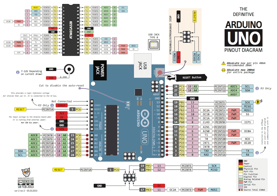
First I started with MCU and digital and analog IO pin headers. Arduino UNO has clever pin headers layout which nicely matches the layout of ATMEGA328 28-DIP package. So no wires need to be crossed. Using a paper template this was an easy part.
The only external component for ATmega328 to work is external 16MHz oscillator that needs two 22pF capacitors. This was the first component that raised above the base plain. Minimal hardware for ATmega328P is done. It was time for a first test with USBasp programmer via AVR ISCP interface.
I made myself a special jig that holds the pin header in place leaving enough room for soldering - "Freeduino shield".
ATmega328 is powered by 5V. Arduino UNO has two power input sources - 7-12V jack or 5V via the USB connector. It also provides a 3.3V power supply for external components. This means 2 power regulators. First to convert 7-12V to 5V and second to convert 5V to 3.3V. I've used two AMS1117 5V and 3.3V regulators with some capacitors according to recommendations in datasheets.
To make it easier I've soldered the power circuit outside the board and then put it above the data lines. This actually created a two-layer free-form circuit. I omitted both the auto-select and reverse current protection parts because it would make it all quite complicated. They are not needed unless you are not nice to your board.
USB to UART circuitThis one is important if you want to upload your sketches via Arduino IDE without use of a programmer. Well, without it it wouldn't be so cool. Original Arduino UNO R3 uses ATMEGA8U2-MU which is great but too small and unsuitable for free-form circuits. I've decided to go with CH340C chip. It has suitable SOP-16 package and only requires four external components - debouncing capacitor, reset capacitor and two Tx/Rx line resistors. The fact no external capacitor is needed simplifies the whole circuit a lot.
I don't like those large THT LEDs so I decided to use small SMD 1206 ones to signal power, L, Tx, Rx communication. I've regretted that a lot. I first soldered an SMD resistor to them and then try to solder it to wires. It was quite tricky. I had to use low temperature of solder iron and be quick about that otherwise the other side of the SMD component got desoldered.
First I connected an external power source to check power regulators. All the voltage levels were fine, so I continued by connecting and USBasp programmer to upload a bootloader into the chip. Surprisingly the chip communicated on the first try. That was a good sign. External crystal works and all pins are connected correctly. The last step was to connect the USB cable and try to upload a blinky sketch. See it yourself:
Now I am going to encase it into clear resin to make it less fragile.
I am Jiri Praus.
Comments