

Hardware components | ||||||
 |
| × | 1 | |||
 |
| × | 1 | |||
 |
| × | 1 | |||
 |
| × | 1 | |||
 |
| × | 1 | |||
 |
| × | 1 | |||
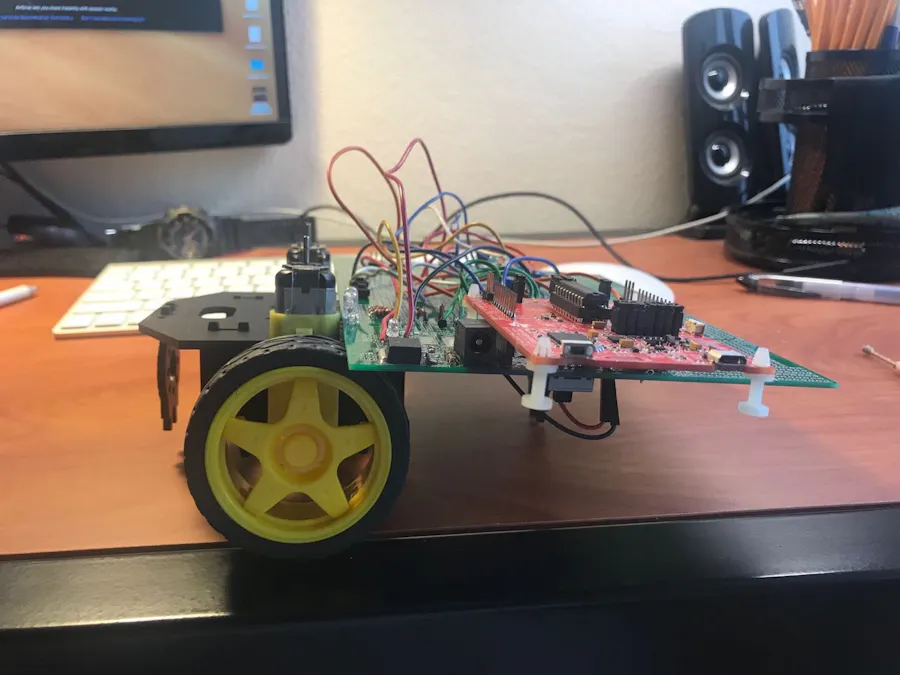
This project is about built a robot that can follow the light, but I damaged the board when I solder chips, so there is one motor can spin in the meantime.
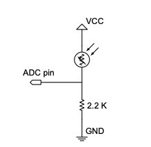
First of all, I solder the photo sensor on the green board and also the H bridge circuit, so it can connect the motor to the MSP430G2553 launchpad.
Secondly, I write some code on C to control motor.
Finally, I did some tests that make sure the motor will work as expect.
#include "msp430g2553.h"
#include "UART.h"

void print_every(int rate);

char newprint = 0;
long NumOn = 0;
long NumOff = 0;
int statevar = 1;
int timecheck = 0;
char textChange = 0;

 void main(void) {

	WDTCTL = WDTPW + WDTHOLD;                 // Stop WDT

	if (CALBC1_16MHZ ==0xFF || CALDCO_16MHZ == 0xFF) while(1);

	DCOCTL = CALDCO_16MHZ;    // Set uC to run at approximately 16 Mhz
	BCSCTL1 = CALBC1_16MHZ;

	// Initialize Port 1
//	P1SEL &=;  // See page 42 and 43 of the G2553's datasheet, It shows that when both P1SEL and P1SEL2 bits are zero
//	P1SEL2 &= ~0x28; // the corresponding pin is set as a I/O pin.  Datasheet: http://coecsl.ece.illinois.edu/ge423/datasheets/MSP430Ref_Guides/msp430g2553datasheet.pdf
//    P1REN |= 0x40;  // resistors enabled for photo-resistor
//	P1DIR |= 0x4; // Set P1.0 to output to drive LED on LaunchPad board.  Make sure shunt jumper is in place at LaunchPad's Red LED
//	P1DIR &= !0x80;
//	P1OUT &= ~0x28;  // Initially set P1.3 to 0

	//initialization for port 1
	P1SEL = 0;
	P1SEL2 = 0;
	P1REN = 0x0;
	P1DIR = 0x12;
	P1SEL |= 0x02;
	P1OUT &= ~0x01;


	//initialization for port 2
	  P2SEL  &= ~BIT6;              // Clear P2.6 in P2SEL  (by default Xin)
	  P2SEL2 &= ~BIT6;              // Clear P2.6 in P2SEL2
	  P2DIR  |=  BIT3+BIT4+BIT6; // P2.3,P2.4,P2.6 all output
	  P2OUT  &= ~BIT3 + BIT4+ BIT6; // Clear P2.3,P2.6 and P2.4
//	  P2OUT &= ~BIT2 + BIT6; // P2.3 = 1,P2.4 = 0


//	ADC10CTL0 = SREF_0 + ADC10SHT_1 + ADC10IE + ADC10SC + ADC10ON;
//	ADC10CTL1 = INCH_3 + ADC10DIV_0;

    ADC10CTL0 =  ADC10SHT_1  + ADC10ON  + ADC10IE +SREF_0 ;//REFON //MSC//REFOUT        +ADC10IE; // ADC10ON, interrupt enabled
    ADC10CTL1 = INCH_3 ;//+ SHS_0  + ADC10DIV_0 + ADC10SSEL_0 + CONSEQ_0;                       // input A0
    ADC10AE0 = 0x08;                         // PA.1 ADC option select

	// Timer A Config
//	TACCTL0 = CCIE;       		// Enable Periodic interrupt
//	TACCR0 = 16000;                // period = 1ms
//	TACTL = TASSEL_2 + MC_1; // source SMCLK, up mode
//	TA0CCR0 = 1000;
//	TA0CCTL1 = OUTMOD_7;
//	TA0CCR1 = 500;
//	TA0CTL = TASSEL_2 + MC_1;


    TACCTL0 = CCIE;                 // Enable Periodic interrupt
    TACCR0 = 16000;                // period = 1ms

    TACTL = TASSEL_2 + MC_1;        // source SMCLK, up mode

    TA1CCR0 = 1600;                 // PWM Period 10Khz
    TA1CCTL1 = OUTMOD_7;            // TA1CCR1 reset/set
    TA1CCTL0 = 0;
    TA1CCR1 = 1000;              // TA1CCR1 PWM duty cycle
    TA1CTL = TASSEL_2 + MC_1;     // SMCLK, up mode

	Init_UART(115200,1);	// Initialize UART for 115200 baud serial communication

	_BIS_SR(GIE); 		// Enable global interrupt


    while(1) {  // Low priority Slow computation items go inside this while loop.  Very few (if anyt) items in the HWs will go inside this while loop

// for use if you want to use a method of receiving a string of chars over the UART see USCI0RX_ISR below
//      if(newmsg) {
//          newmsg = 0;
//      }

        // The newprint variable is set to 1 inside the function "print_every(rate)" at the given rate
        if ( (newprint == 1) && (senddone == 1) )  { // senddone is set to 1 after UART transmission is complete

            // only one UART_printf can be called every 15ms
            //UART_printf("St%d On %ld Off %ld\n\r",statevar,NumOn,NumOff);
            if(textChange == 0)
                UART_printf("nothing\n\r");
            if(textChange == 'd')
                UART_printf("dark\n\r");
            if(textChange == 'l')
                UART_printf("light\n\r");
//            UART_printf("%c",mytext);
            newprint = 0;
        }

    }
}


// Timer A0 interrupt service routine
#pragma vector=TIMER0_A0_VECTOR
__interrupt void Timer_A (void)
{
//    timecheck++; // Keep track of time for main while loop.
//    print_every(500);  // units determined by the rate Timer_A ISR is called, print every "rate" calls to this function
//
//    switch (statevar) {
//        case 1:  //LED ON
//
//            P1OUT |= 0x1;  // really do not have to turn on the LED each time in here but making the point that this is the functionality of statevar = 1
//            NumOn++;
//            if (timecheck == 500) {  // if statement to determine what the state should be the next millisecond into the Timer_A function
//                timecheck = 0;
//
//                statevar = 2;  // Next Timer_A call go to state 2
//            } else {
//                statevar = 1;  // stays the same.  So not really needed
//            }
//            break;
//        case 2:  //LED OFF
//
//            P1OUT &= ~0x1;  // really do not have to turn off the LED each time in here but making the point that this is the function of statevar = 2
//            NumOff++;
//            if (timecheck == 250) {  // if statement to determine what the state should be the next millisecond into the Timer_A function
//                timecheck = 0;
//
//                statevar = 1;
//            } else {
//                statevar = 2;  // stays the same.  So not really needed
//            }
//            break;
//    }
    ADC10CTL0 |= ENC + ADC10SC;

}

#pragma vector=ADC10_VECTOR
__interrupt void ADC10_ISR(void) {
    timecheck++; // Keep track of time for main while loop.
    print_every(250);  // units determined by the rate Timer_A ISR is called, print every "rate" calls to this function

    int ADCraw = ADC10MEM;
    int ADC = (3300L*ADCraw)/1023;

    switch (statevar) {
    case 1: // when the photo sensor covered with darkness
        P1OUT &= ~0x12; //stop the motor
        P2OUT &= ~BIT3 + BIT4;
        if ((ADC > (3300/4)) && (ADC < (3300/2))){
            statevar = 2;
        }
        if( ADC > (3300/2)){
            statevar = 3;
        }

        break;
    case 2:
        if (ADC < 3300/4){
            statevar = 1;
        }
        if (ADC > 3300/2){
            statevar = 3;
        }
        break;

    case 3 :        // when the photo sensor detect the light
        P1OUT |= 0x12; // start the rotation
        P2OUT |= BIT4;
        P2OUT |= BIT6;


        if (ADC < 3300/4){
            statevar = 1;
        }
        if ((3300/4 <ADC) && (ADC< 3300/2)){

            statevar = 2;
        }
        break;


    }
}


// USCI Transmit ISR - Called when TXBUF is empty (ready to accept another character)
#pragma vector=USCIAB0TX_VECTOR
__interrupt void USCI0TX_ISR(void) {

	if(IFG2&UCA0TXIFG) {		// USCI_A0 requested TX interrupt
		if(printf_flag) {
			if (currentindex == txcount) {
				senddone = 1;
				printf_flag = 0;
				IFG2 &= ~UCA0TXIFG;
			} else {
				UCA0TXBUF = printbuff[currentindex];
				currentindex++;
			}
		} else if(UART_flag) {
			if(!donesending) {
				UCA0TXBUF = txbuff[txindex];
				if(txbuff[txindex] == 255) {
					donesending = 1;
					txindex = 0;
				}
				else txindex++;
			}
		} else {  // interrupt after sendchar call so just set senddone flag since only one char is sent
			senddone = 1;
		}

		IFG2 &= ~UCA0TXIFG;
	}

	if(IFG2&UCB0TXIFG) {	// USCI_B0 requested TX interrupt (UCB0TXBUF is empty)

		IFG2 &= ~UCB0TXIFG;   // clear IFG
	}
}


// USCI Receive ISR - Called when shift register has been transferred to RXBUF
// Indicates completion of TX/RX operation
#pragma vector=USCIAB0RX_VECTOR
__interrupt void USCI0RX_ISR(void) {

	if(IFG2&UCB0RXIFG) {  // USCI_B0 requested RX interrupt (UCB0RXBUF is full)

		IFG2 &= ~UCB0RXIFG;   // clear IFG
	}

	if(IFG2&UCA0RXIFG) {  // USCI_A0 requested RX interrupt (UCA0RXBUF is full)

//    Uncomment this block of code if you would like to use this COM protocol that uses 253 as STARTCHAR and 255 as STOPCHAR
/*		if(!started) {	// Haven't started a message yet
			if(UCA0RXBUF == 253) {
				started = 1;
				newmsg = 0;
			}
		}
		else {	// In process of receiving a message
			if((UCA0RXBUF != 255) && (msgindex < (MAX_NUM_FLOATS*5))) {
				rxbuff[msgindex] = UCA0RXBUF;

				msgindex++;
			} else {	// Stop char received or too much data received
				if(UCA0RXBUF == 255) {	// Message completed
					newmsg = 1;
					rxbuff[msgindex] = 255;	// "Null"-terminate the array
				}
				started = 0;
				msgindex = 0;
			}
		}
*/

		IFG2 &= ~UCA0RXIFG;
	}

}

// This function takes care of all the timing for printing to UART
// Rate determined by how often the function is called in Timer ISR
int print_timecheck = 0;
void print_every(int rate) {
    if (rate < 15) {
        rate = 15;
    }
    if (rate > 10000) {
        rate = 10000;
    }
    print_timecheck++;
    if (print_timecheck == rate) {
        print_timecheck = 0;
        newprint = 1;
    }

}


Comments