IntroMy family and I enjoy visiting the beach, especially on hot summer days. We always bring out a cooler full of ice and cold drinks, which are extremely refreshing when sitting on the beach for a long time on a hot day. However, we sometimes find the drinks hotter than they should be, and we also sometimes forget to close our cooler, making the ice melt a lot quicker.
(Photo from Wikimedia to make this long section more interesting)
For this contest I decided to build a device that will remind us to close the lid of the cooler, allow us to monitor the temperature from our phones, and also play a loud, obnoxious noise when someone tries to move the cooler.
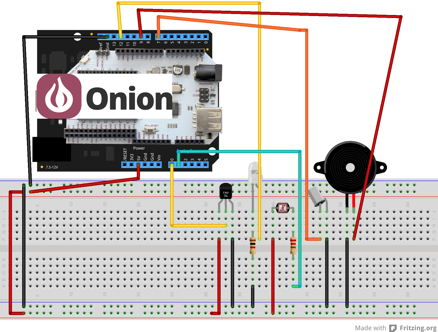
Part 1The heart of this device is the Omega 2+, which I used with an Arduino Dock 2 to make the programming and connectivity with sensors easier. Ignoring the messy wires in the picture below, you can see the Omega 2+ (covered by a piece of paper because my information is written on it) on the Arduino Dock 2 connected to a photoelectric sensor, a piezo buzzer, a very accurate temperature sensor, and a tilt sensor. A more clear schematic is also included below. The LED is also included for testing (so my ears are not damaged by the very obnoxious noise from the buzzer); when the buzzer is supposed to be silent, the LED is on.
Sorry for the messy wiring, but this is my project.
The temperature data is sent via WiFi to Losant, so you can view the temperature data in a graph as well as in real time from your phone. The graph (of temperature readings when the device is in a hot room) is shown below.
Graph of temperature data sent to Losant from the temperature sensor
In order to set up Losant, I used the tutorial on Onion's free Omega2 Project Book. The project I followed was the Smart Plant project, and I modified the code to fit my needs. My code is linked below. If you follow it, be sure to add in your own Losant device ID, key, and secret code into the losant.json file (not included in my github repository).
ConclusionsIn the future, the OLED expansion can be added on top of the Omega2+ to allow you to view temperature data without your phone or an internet connected device, as well as a GPS module connected to the USB port so you can locate the cooler if someone does steal it. I will also be 3D printing a case to install this project in my family cooler.


Comments