

Hardware components | ||||||
| × | 1 | ||||
Software apps and online services | ||||||
 |
| |||||
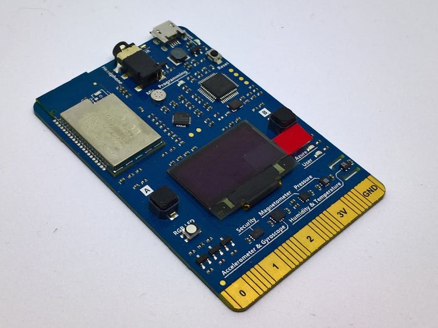
I’ve been looking forward to the release of the Azure AZ3166 “MXChip IoT DevKit” – a device with lots of sensors and outputs built into the device, that I can securely connect to IoT Hubs in the Azure cloud.
I’ve a few different posts planned about this device – in this post, I’ll write about the installation process, some small issues I found and a basic application to interact with on-board LEDs by configuring pins as digital outputs.
The device has these on-board features:
- A temperature and humidity sensor (HTS221)
- A pressure sensor (LPS22HB)
- An accelerometer and gyroscope (LSM6DSL)
- A magnetometer (LIS2MDL)
- Two buttons
You can read more about the Azure AZ3166 here.
So because these are all on-board, that makes accessing them and using them really easy (particularly because all of the items above have great API documentation, and most have example code).
A couple of the features of this device I found very interesting were compatibility with Arduino code, and the connecting finger which has the same form factor as the BBC micro:bit – I’d like to find out how I can use this device to work with some of the breakout boards I use with my Arduino.
Software installation and getting startedThere’s already a really good description of how to get started with this kit – check it out here. There’s no point in me repeating all of that here, so in summary:
- Connect the device to your WiFi and check that it’s working.
- Download and install the latest tools, drivers and packages for the DevKit device.
This almost perfectly worked out of the box for me – but I like to share the small issues I experienced because I hope they’ll be road-signs that help other developers avoid spending time on the same problems.
- The DevKit only works on 2.4GHz Wi-Fi. This is in the FAQ, but I didn’t read this right off the bat, and spent some time wondering why my hardware couldn’t find my Wi-Fi. Turned out that it was because I was running both 2.4GHz and 5GHz signals out of my router – when I changed the router settings to only broadcast on 2.4GHz, my device found the Wi-Fi straight away.
- There are lots of warnings when you try to compile any application for the device through the Arduino or VSCode environments. The Arduino compiler output, even for ‘Hello World’ type applications, was absolutely littered with warnings. I’ve pasted a few below.
#warning toolchain.h has been replaced by mbed_toolchain.h, please update to mbed_toolchain.h [since mbed-os-5.3]
...
#warning wait_api.h has been replaced by mbed_wait_api.h, please update to mbed_wait_api.h [since mbed-os-5.3]
...
#warning sleep.h has been replaced by mbed_sleep.h, please update to mbed_sleep.h [since mbed-os-5.3]
...
#warning rtc_time.h has been replaced by mbed_rtc_time.h, please update to mbed_rtc_time.h [since mbed-os-5.3]
I spent some time uninstalling and re-installing different programs, and I even to the extent of installing the software on a fresh instance of Windows 10 in case another application or library conflict was causing this – it made no difference. But ultimately, these warnings didn’t impact any applications that I deployed.
- Problems displaying serial output in the Arduino IDE Serial Monitor. I’m used to deploying applications to the Arduino using the Arduino IDE, specifically targeting a COM port at deployment time. I created an application for the AZ3166 with a few “Serial.println” statements, hoping to use the Serial Monitor built into the Arduino IDE to read the output. But after deploying to the AZ3166 DevKit device, I tried to open the Serial Monitor, and got an error message saying the IDE couldn’t find the COM1 port. The solution was to manually set the COM port through the “Tools -> Port” sub-menu, as the default port selected by the IDE isn’t actually the port that serial output is sent through.
There is already an example for the on-board RGB LED, but I wanted to work at a lower level to access on-board LEDs, rather than using existing libraries. I just needed to find out what Arduino pin numbers corresponded to the LEDs on the DevKit device.
I found that the numbers corresponding to the three basic LED colors are:
- Red LED – Arduino pin 20
- Green LED – Arduino pin 19
- Blue LED – Arduino pin 39
I’ll post more about DevKit to Arduino pin mappings in a later post.
With this knowledge, it was very simple to create a variation on the standard “blinky” application, where I turn the red LED on and off, then the green LED, and finally the blue LED.
I’ve pasted the code below – just like regular Arduino C code.
int RED_LED = 20;
int GREEN_LED = 19;
int BLUE_LED = 39;
void setup() {
  // initialize the pins as digital output.
  pinMode(RED_LED, OUTPUT);
  pinMode(GREEN_LED, OUTPUT);
  pinMode(BLUE_LED, OUTPUT);
}
void loop() {
  // turn red LED on
  digitalWrite(RED_LED, HIGH);
  delay(1000);
  // turn red LED off
  digitalWrite(RED_LED, LOW);
  delay(1000);
  // turn green LED on
  digitalWrite(GREEN_LED, HIGH);
  delay(1000);
  // turn green LED off
  digitalWrite(GREEN_LED, LOW);
  delay(1000);
  // turn blue LED on
  digitalWrite(BLUE_LED, HIGH);
  delay(1000);
  // turn blue LED off
  digitalWrite(BLUE_LED, LOW);
  delay(1000);
}
Hopefully this helps you get started with the AZ3166 DevKit - I'll be writing more about this device soon.


Comments