

From time to time, I start a project to try to make some kind of automated robotic walker (like an AT-AT, but I'm aiming for something about the size of a cat, if you can imagine such a thing). I design the body, 3d print it, attach the servos, start programming...and at this point I normally run into problems. I need my servos to move to some precise positions - or at least behave consistently on each leg of the robot - but in practice, I've found the legs don't behave the way I'd expect. I decided to carry out a simple experiment to investigate just how inconsistent my servos are.
To do this, I needed to build a test rig which could hold my servos (I need space for 8 servos, two for each of the robot's four legs). I control my servos using the Adafruit PWM Servo controller shield (which can control up to 16 servos). This shield is mounted on my Arduino Duemilanove (it's a bit old now, but still works for 99% of my projects), which is powered and controlled by my computer's USB port. The Adafruit Servo controller shield needs a separate power supply of about 5v - 6v - I've used a LM2596 DC-DC Step down voltage converter with a 9v battery to get the necessary voltage.
Designing and printing the rigFirst - I designed a rig which would hold my 9v battery, my LM2596 voltage converter, my Arduino and eight servos. After some tinkering in Autodesk 123D, I came up with the rig below. You can see I've positioned holes to securely attach my Arduino, and there are also 2.9mm holes along the back to allow me to attach my servos (which have 3mm shoulder holes).
I sent this to my Prusa i3 Mk2 3d printer, and the finished item on the print bed is shown below.
And here it is removed from the print bed.
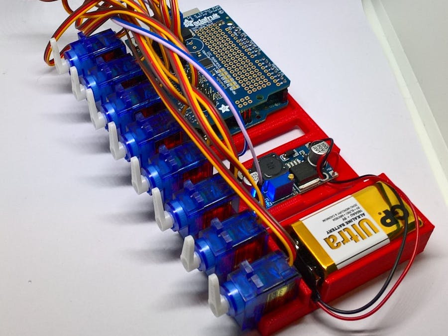
I attached all the components - the Arduino and Adafruit Servo shield, the LM2596 controller, the 9v battery, and finally the eight 9g servos. Now I have a fairly neat rig that I can control and observe the behavior of my servos.
Now everything was attached to the rig, the last step was to make sure that all servos were turned to their maximum counter-clockwise position, and attach a wiper to the servos. (I positioned the servos in my design to be just far enough apart so that the wipers don't collide with each other). The image below shows all eight servos in their starting position.
Using my Arduino IDE, I installed the Adafruit PWM Servo Driver Library (from the Sketch menu, I selected Include Library and then Manage Libraries...., and installed the library from the Library Manager screen.
Then I just selected the default "Servo" project which is built into the library, and following that I compiled and deployed the project to my Arduino. This project has the built in values for pulse lengths - 150 out of 4096 for the minimum position, and 600 out of 4096 for the maximum position.
As you can see in the image below, even though each of the servos was sent a max PWM pulse of 600, they all end up in a slightly different position - some more than 180 degrees, some less.
Being able to see the servos side by side and compare their initial and final positions when each is sent the same PWM signal has been useful to me - it tells me that each of my servos has its own individual profile. To get each servo to act like each of the others, I need to work out the PWM values that corresponds to 0 and 180 degrees, and use interpolation to work out the PWM values needed to move to positions between extremes. I'll look at this in a separate project.
If you like this, check out my blog or my Twitter feed for more!

Comments