


In this exercise, assembly language code was executed on the STM32F407ZGT6 microcontroller using the RT-Thread RT-Spark development board. The STM32CubeIDE debugger was utilized to observe program execution at the processor level, allowing detailed examination of register values, memory contents, instruction flow, and processor behavior during runtime.
The activity aimed to provide a deeper understanding of how software instructions are executed by the ARM Cortex-M4 processor. Through debugging and step-by-step execution, it was possible to analyze how data moves between registers and memory, how arithmetic and logical operations are performed, and how control flow instructions affect program execution.
STEPS:
- First, create a project in CubeMx
- Second, it will directly go to MCU/MPU Selector. Then, in Commercial Part Numberyou have to put STM32F407ZGT6 then choose the first one in the lists.
- Next, Pin out & Configuration.
- Set pin PF11 and PF12 as GPIO_OUTPUT. Then set the label of PF11 into LED_RED and PF12 into LED_BLUE.
- Go to Timer 2 (TIM2) and configured to generate periodic interrupts. In STM32CubeMX, TIM2 was selected under the Timers section and its clock source was set to Internal Clock. The timer parameters were then configured by setting the Prescaler (PSC) to 8399 and the Counter Period (ARR) to 9999, resulting in a timer frequency of 1 Hz, which generates an interrupt every second. Next, the TIM2 global interrupt was enabled in the NVIC Settings tab, and its priority was set to 0, making it the highest-priority interrupt in the system. Finally, the project code was generated by selecting Project → Generate Code.
Start the Timer with Interrupt-Enabled
Access the main.c file of the generated project and add the required code to initialize and start the timer. The HAL_TIM_Base_Start_IT() function is used to start the timer in base mode with interrupts enabled, allowing the timer to count and automatically generate an interrupt whenever the configured period is reached. This mode is intended for basic timing operations and does not utilize the advanced features available in other timer modes.
1. What is TRelease for the timer ISR? (When is it ready to run)?
TRelease is a parameter used to capture the timestamp at which the hardware timer interrupt begins generating signals that trigger the Timer ISR. In this context, TRelease corresponds to the moment when the timer's Auto-Reload Register (ARR) reaches its configured value and generates an interrupt, provided that interrupts are enabled.
2. What is TISR for your callback function? (Use debugger to measure)?
To measure the TISR of a callback function, use the Data Watchpoint and Trace (DWT) unit and inspect the Cycle Count Register (CYCCNT) while debugging. The CYCCNT register records the number of clock cycles (ticks) taken by the function. This tick count can then be converted into time. For a 16 MHz clock, dividing the number of ticks by 16, 000, 000 gives the execution time in seconds, while dividing by 16 gives the execution time in microseconds. In this case, a count of 54 ticks results in a TISR of 3.375 ms.
3. How does this differ from the polling-based LED blink in Lab 0?
The main difference between polling and interrupts is how they handle events. In polling, a function is repeatedly checked within a loop to determine whether an event has occurred. In contrast, an interrupt temporarily halts the normal execution of the program when a specific event occurs. The processor then executes the corresponding Interrupt Service Routine (ISR), and once the ISR has finished, the previously interrupted code resumes execution from where it left off. This allows the system to respond to events immediately without continuously checking for them.
Create a second timer with an interrupt for a multiple Interrupt-Service-Routine (ISR) functions
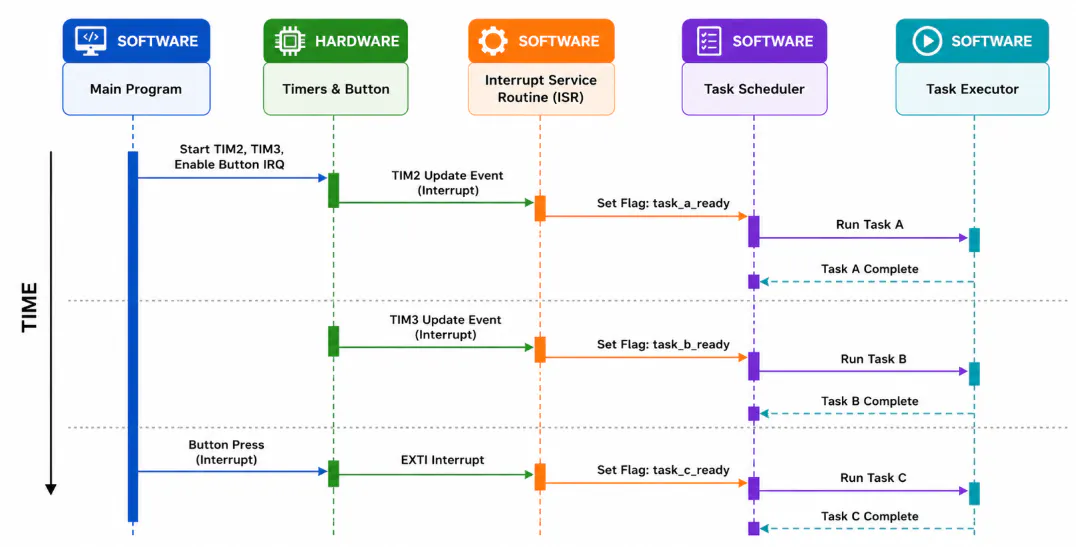
Configure TIM3 as the second timer using the same Clock Source, Prescaler, and Global Interrupt settings as TIM2. Set the Counter Period (ARR) to 4999, which produces a timer period of 0.5 seconds. Assign a Preemption Priority of 1, making it lower in priority than TIM2. In STM32CubeIDE version 1.19.0, you may need to adjust the NVIC priority grouping and allocated priority bits within the NVIC settings, since the priority level cannot always be modified directly from the TIM3 configuration page. This setup ensures that when both timers generate interrupts simultaneously, TIM2 (LED1) is serviced before TIM3 (LED2). After completing the configuration, regenerate the project code. Keep in mind that code generation can overwrite modifications made outside the designated USER CODE sections, so ensure any custom code is placed within those protected blocks.
Write this code within the main.c File, and Build Project.
Measure and analyze the system’s timing parameters.
The procedures in sections (a) to (c) are optional and are only necessary if you have access to an oscilloscope or logic analyzer, both of which require connection to the designated debug pin. If you are using the Data Watchpoint and Trace (DWT) unit for timing measurements, you may skip directly to section (d), as this is the method primarily covered in this guide.
Set PE0 as GPIO_Output, label as “DEBUG_PIN”, and generate code.
Update callback, loop code for Debug_Pin time measurement.
Using the STM32CubeIDE Debugger, place an entry breakpoint at the beginning of the HAL_TIM_PeriodElapsedCallback() function and another breakpoint inside the if (task_adc_ready) block in the main loop. These breakpoints allow you to monitor the time interval between the timer interrupt occurrence and the start of Task A execution, enabling measurement of the system's latency and response behavior.
Measuring Timing Parameters
I.
To measure the TLatency of Task A, which begins from the callback function, the first line of the callback function is assumed to represent the hardware TRelease, as it is the closest point that can be captured in software. The measurement ends at the start of TTask, specifically at the task_adc_ready if statement within the main loop. The highlighted volatile variables are declared globally to allow tick values to be recorded beyond the callback function’s scope and to provide more accurate measurements compared to relying on the debugger’s variable value analyzer. Based on the recorded values, the measured latency is 136 ticks, which corresponds to 136/16 = 8.5 microseconds.
II.
TISR (TIM2) is measured from TRelease, which is assumed to occur at the first line of the callback function, up to the last line of the TIM2 if statement. The recorded execution time is 78 ticks, which corresponds to 78/16 = 4.875 microseconds.
III.
TResponse (Task A) is measured from TRelease, which is assumed to be the first line of the callback function, up to the end of TTask, represented by the final line of the `task_adc_ready` if` statement in the main loop. Although DWT measurements combined with `HAL_Delay() need to be recorded locally, the response time can still be determined directly by adding TLatency and TTask. As a result, TResponse is equal to (136 ticks/16 [converted to fAPB microseconds] + 50 ms) = 50.0085 ms.
1. What is the maximum latency for Task A in your system?
To measure the maximum latency of Task A without specialized measurement equipment, the DWT debugger can be used. The first timestamp is recorded at the beginning of the TIM2 callback function’s if statement, while the second timestamp is taken at the start of the task_adc_ready if statement in the main loop. A variable can then be used to track the maximum observed latency by updating it whenever the current latency exceeds the previously stored maximum value. Using this method, the highest latency measured for Task A including delays introduced by other tasks such as Task B was 332, 604 ticks / 16, equivalent to 20.7 ms. The lowest measured latency was 404 ticks / 16, corresponding to 25.2 ms.
2. If Task B is running when TIM2 interrupt occurs, how does it affect TLatency(Task A)?
Because TIM2 has a higher priority, it can preempt TIM3 even while TIM3 is executing, provided interrupts are enabled. In this case, TIM3 execution is temporarily suspended (assuming run-to-completion is enabled), allowing the TIM2 interrupt to be serviced immediately by its corresponding software ISR. As a result, the interrupt latency (T Latency ) is reduced.
3. Calculate worst-case TResponse for Task A if all other tasks are running 4. How would response time change with a preemptive scheduler? To determine the TResponse of Task A while all tasks are active, we use the result from #1, which gives the maximum TLatency of Task A. Since the TTask of Task A is 50 ms due to its delay interval, we can calculate the maximum TResponse by adding the TTask and the maximum TLatency. Thus, the maximum TResponse of Task A is 20.7 ms + 50 ms, resulting in 70.7 ms.
4. In this scenario, which uses a priority-based preemptive scheduler, TLatency is affected by how long a task has to wait from TRelease (when the task becomes ready) before its interrupt is recognized and its ISR starts running. Since the scheduler is preemptive and tasks are assigned different priority levels, higher-priority tasks usually have lower TLatency and TResponse Time because they are serviced first. TLatency is the time from TRelease until the ISR begins execution, while TResponse Time is the total time from TRelease until the ISR has completely finished executing.
Create an Event-Triggered Scheduling
To implement event-triggered scheduling, configure an external interrupt using a GPIO pin. Set PA0 as GPIO_EXTI0, configure the GPIO mode to Rising Edge Triggered External Interrupt, enable the interrupt, and set the GPIO pull configuration to Pull-Down. Assign a Preemption Priority of 2 and regenerate the project code. For the RT-Spark 1 Development Board, since PA0 is not connected to a physical button, an alternative button pin such as PC1 (Down), PC0 (Left), PC4 (Right), or PC5 (Up) may be used instead. When using these pins, configure the GPIO mode as Falling Edge Triggered External Interrupt, set the pull configuration to Pull-Up, enable the interrupt, and regenerate the code after completing the configuration.
1. Compare response time of button press (event-triggered) vs. timer flags (polled)
In this setup, timer interrupts typically only set flags that are later checked by the main loop in a cyclic execution model, meaning tasks run only when the loop allows it. In an event-triggered approach, the interrupt executes the task code directly, which can reduce latency but may make TISR and TTask effectively the same. However, a priority-based pre-emptive system can require more memory to manage task states and may risk delays or hangs due to shared bus contention. Overall, the best method depends on the system’s requirements and constraints.
2. What is the advantage of interrupt-based event handling?
Using interrupt-based events reduces CPU workload because the processor does not need to continuously poll for conditions. Instead, the CPU only executes the relevant code when an interrupt signal occurs.
3. How does the priority system affect which ISR runs first?
Priority-based scheduling helps reduce the TResponse of high-priority tasks by allowing them to preempt lower-priority ones instead of waiting for them to finish. Since TLatency strongly influences overall response time, giving priority to critical tasks improves their responsiveness.


Comments