

Hardware components | ||||||
| × | 1 | ||||
 |
| × | 1 | |||
 |
| × | 1 | |||
See also:
Part 1. The I/O configurator
Part 2. Monitor I/O by serial monitor and VBA debugger
Part 4. The heater control
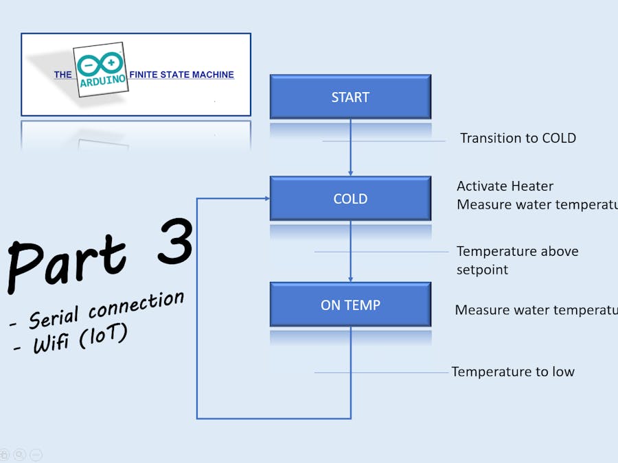
This part (Part 3) is about the connection between the board and the desktop. Just a necassery part, before going to the theory, the design and the realization of controls based on a finite state machine. As writen in part 2, it is possible to present the defined I/O, mask and force the datapoints. In this -bit of boring- part, the connection between the MEGA 2560 board and the desktop is described. I've made 2 types of connections; serial and IP (WiFi). There are a few differences between the serial connection and the IP connection; the IP connection is less reliable and less quick. The IP connection is sometimes lost and has to be connected again (with some loss of data; maybe a databuffer is necassery in the future to prevent the loss of data.... but... time).
The serial connectionAs an example a TTL to USB connection can be made to connect to the PC, but also possible is a bluetooth connection or a connection made up by a radio connection set APC220 (for the longer distances). All connections have one thing in common; they communicate via a COM port on the PC. Not explained are installing the software for the TTL to USB module (mostly a CP210x) and how to determine the right com port. Google gives a lot of information. Important for the connection are some settings you have to make on the PC. Setting can be made on 2 different places on the PC.
Method 1. When working in the Visual Studio environment, the communication settings has to be made in the project property form. Be aware of the version you use; there is a debug and a release version. Up to you what you use. When the solution is build as the debug version, visual studio gives you a lot of extra possibilies for debugging your application; but the disadvantage is the fact that everything is bit slower:
After click HMI properties (be sure you have the focus on the right project), you will get the following screen. Again; be aware of the chosen configuration (Release or debug):
In this screen, you have to give the portname, the baudrate of Serial1 in the sketch and the monitor parameter. The monitor parameter will determine the setting of getting all known datapoints from the sketch and present them all on the debug screen. If monitor is set as NO, there will be no datafields on the debug form; this opens the possibility to make your own scada form, by placing the datapoints of your choice on the screen (and do some funny VBA tricks, with the data...). The way how to make your own scada screen is on my website.
Method 2. Another possibility is getting the .exe file out of the solution, make a shortcut on your desktop and add the command line arguments. Like the example below. Be aware of the version you get out of the solution folder; there is a debug and a release version folder.
The software on the Sketch and also the Configurator, is identical to the "serial" version of the AFSM. There is one more project present in the solution; the WiFi ketch. You have to build and load this sketch apart from the MEGA 2560 sketch. There is no luxury way to change the SSID and password for your home router; you have to change this in the Wifi .ino sketch. Where the TTL to USB is communicating via serial, the ESP8266 is doing the same based on IP.
So only the HMI application is different. The app is not called HMI but IoT in the Visual Studio solution. There is no comport used but the IP stack. Like the serial version, there is a module used for communication. In this case an ESP8266. The ESP8266 is making connection to the home router and will be listening to data from the desktop. For the proper settings of the communication, you have to set some communication parameters; the ipadress and the port number (default 1500). The method is identical as for the serial version. You can make the setting in the Visual Studio environment as well as adding command line arguments to the shortcut.
The ipadress of the ESP8266 can be obtained from your home router. See the example below, the ESP is present as ip 192.168.178.67 in the router:
When starting the IoT app, you got something like below:
The next part of the Arduino Finite State machine is about the theory and make of a Finite State machine control. See also www.jbsiemonsma.nl


Comments