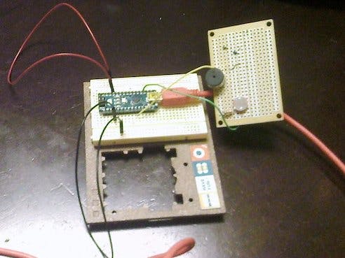
The nano light theremin is a variation of the light theremin project described in the starter kit. I liked the project so much, I decided to build a more permanent variation. I soldered a piezo buzzer, resistor and photocell onto a PCB and added wires.
If you use a PCB: one leg of the 10 kOhm resistor is connected to one of the photocell's legs. A wire connects the other leg of the photocell with the ground pin of the piezo buzzer.
The project uses the same code as the light theremin project in the starter kit. Once you have uploaded the code, you might want to wave a hand over the photocell and notice any variations in sound.
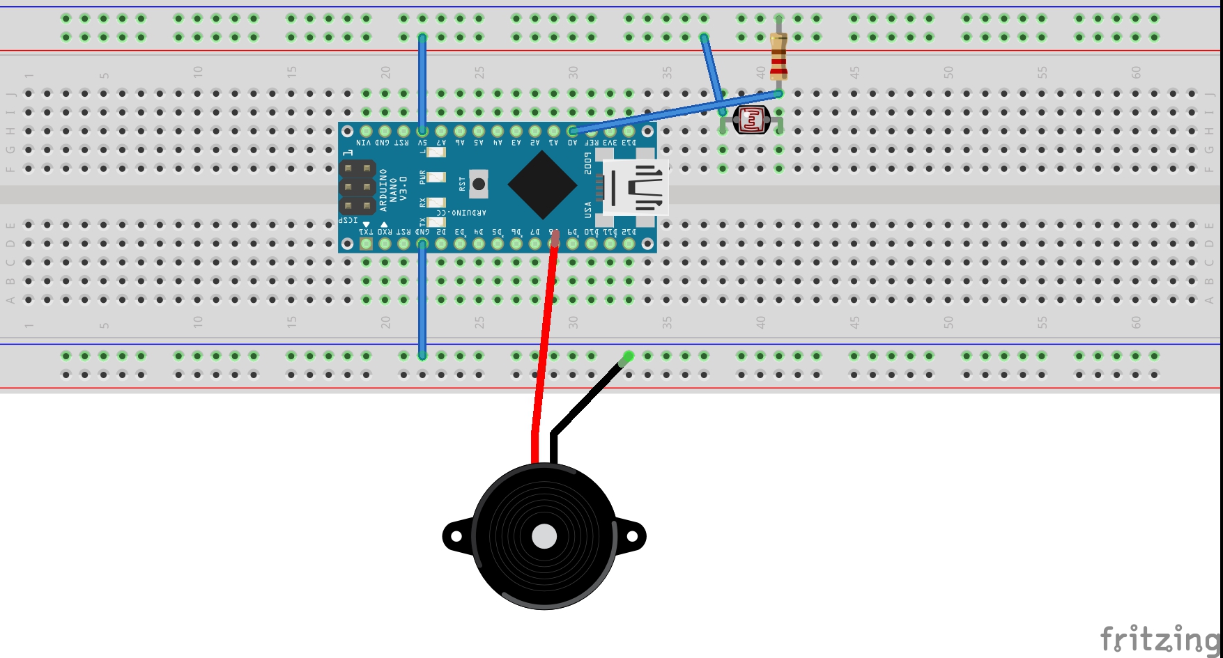
The prototype features jumper wires. If you are using a solderless breadboard, you can place the Nano in the middle of the board itself. Add the lead from the resistor to A0 and the power (+) lead from the buzzer to pin 8.
As another variation, you might consider soldering the leads for A0 and pin 8 directly onto the Nano itself, as I have done. If you would rather preserve the Nano for other projects, perhaps using a solderless bread board is the best option.
Hopefully this can help you setting up the board. If you can find the light theremin project in the book accompanying the starter kit, the diagram and instructions there might help as well. The only difference, once again, is the board: a Nano substituting in for the Uno.
This code is from the Arduino starter kit. Once you upload it, the buzzer will start making sounds. Wave a hand over the photocell for sound variations.
/* Arduino Starter Kit example Project 6 - Light Theremin This sketch is written to accompany Project 6 in the Arduino Starter Kit Parts required: photoresistor 10 kilohm resistor piezo Created 13 September 2012 by Scott Fitzgerald http://www.arduino.cc/starterKit This example code is part of the public domain*/// variable to hold sensor valueintsensorValue;// variable to calibrate low valueintsensorLow=1023;// variable to calibrate high valueintsensorHigh=0;// LED pinconstintledPin=13;voidsetup(){// Make the LED pin an output and turn it onpinMode(ledPin,OUTPUT);digitalWrite(ledPin,HIGH);// calibrate for the first five seconds after program runswhile(millis()<5000){// record the maximum sensor valuesensorValue=analogRead(A0);if(sensorValue>sensorHigh){sensorHigh=sensorValue;}// record the minimum sensor valueif(sensorValue<sensorLow){sensorLow=sensorValue;}}// turn the LED off, signaling the end of the calibration perioddigitalWrite(ledPin,LOW);}voidloop(){//read the input from A0 and store it in a variablesensorValue=analogRead(A0);// map the sensor values to a wide range of pitchesintpitch=map(sensorValue,sensorLow,sensorHigh,50,4000);// play the tone for 20 ms on pin 8tone(8,pitch,20);// wait for a momentdelay(10);}


Comments