

Software apps and online services | ||||||
| ||||||
 |
| |||||
Many embedded device developers suffer from making a STM32CubeIDE Project and so do I.
Recently, I needed to make a new project and decided using STM32CubeIDE because it is freeware and has a lot of useful features.
I think the whole process may be helpful to newbies in embedded devices and share what I did as a tutorial.
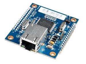
I had to make a project for WIZ145SR from WIZnet and it consists of STM32 MCU and W5300 Ethernet Controller.
Below is the tutorial of the whole process from MCU selection, to Clock Configuration, GPIO setting, Printf configuration, Timer setting, UART transmission and so on.
Please follow below step by step.
Build a New ProjectFirst, select File->New->STM32 Project to make a new project like below image.
Target Selection Window pops up automatically and waits for you to choose a MCU you want. Please check "Arm Cortex M3" in Core section, "STM32F103" in Line section, and select STM32F103ZE LQFP144 package on the right plane.
MCU SelectionAfter selected, the window will change as below.
After MCU selecteion, you should do Clock Configuration.
WIZ145SR has 8MHz External Oscillator on it and its main clock becomes 72MHz via PLL.
Select High Speed ClockClick Pinout & Configuration Tab and follow System Core->RCC, then select "Crystal/Ceramic Resonator" on High Speed Clock.
Next, click Clock Configuration Tab, then configure as below.
Click HSE on PLL Source Mux, then choose X9 (8MHz X9 = 72MHz) in PLLMul combo box, and select PLLCLK in System Clock Mux.
Then, select /2 in APB1 Prescaler combo box. (Because Maximum frequency of APB1 Peripheral clock is 36MHz.)
Code GenerationChoose "Generate Code" from menu or "Generate Code" icon on the toolbar after Clock Configuration.
This will generate code according to the configuration you did.
Select Project->Build Project on the menu to make a binary code.
DownloadWIZ145SR supports only UART Bootloader to download a binary code..
First, change MCU to Bootloader mode, then download a binary code with STM32CubeProgrammer.
📷In order to use UART Bootloader, you should choose UART like above.
The whole project files so far can be downloaded from the below link on github.com.
https://github.com/javakys/WIZ14xSR_Proj/releases/tag/Ver0.1
WIZ145SR Pinout and MCU Pin ConfigurationPlease refer to below link for WIZ145SR Pinout and MCU Pin map table.
You need to check above table whenever any peripheral is configured.
Printf() configurationprintf(), which is known as stdout, is a popular and common debugging tool. Using external debugger is much better but we use printf() easily because it is available without any external debugger.
From now, I show the whole steps to use printf().
Enable UART2WIZ145SR supports a debug UART for console message as well as data communication UARTs. Console port is the UART2.
First, set USART2 up as below.
Mode is "Asynchronous", Hardware Flow Control is "Disable", and in NVIC Settings, check interrupt "Enabled".In fact, you can set it "Disable" because the console post is used as only printing out.
After configuration, select "Generate Code" menu and update your code.
Selecting "Generate Code" make code including UART2-related one.
n main.c
...
static void MX_USART2_UART_Init(void);
...
Include stdio.h in main.c, in order to use printf().
in main.c
...
#include "stdio.h"
..
write _write() function in USER CODE block of main.c.
/* USER CODE BEGIN 0 */
int _write(int file, char *ptr, int len)
{
	HAL_UART_Transmit(&huart2, (uint8_t *)ptr, len, 10);
	return len;
}
The function to send character to UART peripheral is HAL_UART_Transmit(). If you use huart2, which is UART2 handle, it transmit data in buffer to UART2.
Now, I will print out the value, which is increaseded by 1 every second, to the console port.
The corresponding code is below.
First, declare count variable.
in main.c
...
/* USER CODE BEGIN 0 */
int _write(int file, char *ptr, int len)
{
	HAL_UART_Transmit(&huart2, (uint8_t *)ptr, len, 10);
	return len;
}

uint8_t count = 0;
/* USER CODE END 0 */
in while loop,
count is increased by 1, and it is printed out by printf(), then wait for 1 second. The whole process will repeat.
in main.c
...
while(1)
/* USER CODE END WHILE */
{
    /* USER CODE BEGIN 3 */
	count++;	// increment count
	printf("count: %drn", count);	// print count
	HAL_Delay(1000);	// 1000 ms delay
  }
  /* USER CODE END 3 */
The whole project files so far can be downloaded from the below link on github.com.
https://github.com/javakys/WIZ14xSR_Proj/releases/tag/Ver0.11
Using Timer and LEDUsing delay to make interval is not a good choice for real time system. So no blocking codes in the main block and using Timer to check interval is recommended.
Setting TimerI use TIM2 in this project.
Set it as below
As Main Clock is 72MHz, Interrupt occurs every 1ms with Prescaler 1000 and Counter 72. If you set Counter 7200, Timer Overflow interval is 100ms.
PF7 is connected to Green LED on the top side of WIZ145SR.
Set this pin as GPIO_OUT.
Do "Generate Code" as usual.
Code reviewIn main.h, define GPIO Port and Pin as below.
in main.h
...
/* USER CODE BEGIN Private defines */
#define UART1_CTS_Pin			GPIO_PIN_11
#define UART1_CTS_GPIO_Port		GPIOA
#define UART1_RTS_Pin			GPIO_PIN_12
#define UART1_RTS_GPIO_Port		GPIOA
#define HW_TRIGGER_Pin			GPIO_PIN_0
#define HW_TRIGGER_GPIO_Port	GPIOB
#define STATUS_1_Pin				GPIO_PIN_5
#define STATUS_1_GPIO_Port		GPIOB
#define STATUS_3_Pin				GPIO_PIN_6
#define STATUS_3_GPIO_Port		GPIOB
#define STATUS_4_Pin				GPIO_PIN_7
#define STATUS_4_GPIO_Port		GPIOB
#define STATUS_5_Pin				GPIO_PIN_8
#define STATUS_5_GPIO_Port		GPIOB
#define UART3_CTS_Pin			GPIO_PIN_13
#define UART3_CTS_GPIO_Port		GPIOB
#define UART3_RTS_Pin			GPIO_PIN_14
#define UART3_RTS_GPIO_Port		GPIOB
#define INT_W5300_Pin			GPIO_PIN_0
#define INT_W5300_GPIO_Port		GPIOC
#define LINK_LED_Pin				GPIO_PIN_1
#define LINK_LED_GPIO_Port		GPIOC
#define TX_LED_Pin				GPIO_PIN_2
#define TX_LED_GPIO_Port			GPIOC
#define RX_LED_Pin				GPIO_PIN_3
#define RX_LEDG_GPIO_Port		GPIOC
#define ACT_LED_Pin				GPIO_PIN_4
#define ACT_LED_GPIO_Port		GPIOC
#define UART4_CTS_Pin			GPIO_PIN_8
#define UART4_CTS_GPIO_Port		GPIOC
#define UART4_RTS_Pin			GPIO_PIN_9
#define UART4_RTS_GPIO_Port		GPIOC
#define SW_INPUT_Pin				GPIO_PIN_13
#define SW_INPUT_GPIO_Port		GPIOC
#define RESET_W5300_Pin			GPIO_PIN_6
#define RESET_W5300_GPIO_Port	GPIOF
#define DEBUG_LED_Pin			GPIO_PIN_7
#define DEBUG_LED_GPIO_Port		GPIOF
/* USER CODE END Private defines */
Enable TIM2 Interrupt using HAL_TIM_Base_Start_IT(&htim2); in USER CODE block as below.
in main.c
...
/* Initialize all configured peripherals */
  MX_GPIO_Init();
  MX_USART2_UART_Init();
  MX_TIM2_Init();
  /* USER CODE BEGIN 2 */
  HAL_TIM_Base_Start_IT(&htim2);
  /* USER CODE END 2 */
We need Callback function HAL_TIM_PeriodElapsedCallback() which is called when Timer Overflow occurs.
In Callback function, DEBUG_LED will be Toggled.
in main.c
...
* USER CODE BEGIN 4 */
void HAL_TIM_PeriodElapsedCallback(TIM_HandleTypeDef *htim)
{
	if (htim->Instance == htim2.Instance)
	{
		/* Toggle LEDs */
    HAL_GPIO_TogglePin(DEBUG_LED_GPIO_Port, DEBUG_LED_Pin);
	}
}
/* USER CODE END 4 */
The whole project files so far can be downloaded from the below link on github.com.
https://github.com/javakys/WIZ14xSR_Proj/releases/tag/Ver0.2
Using 4 UARTsNow, I will make an example that sends string to 4 UART every second which is triggered by Timer interrupt.
Setting 4 UARTsSet USART1, USART3, UART4, UART5 as below.
You should set Mode with "Asynchronous", Hardware Flow Control with "Disable", and check interrupt Enabled.
Don't forget do "Generate Code" last.
Current Timer interrupt occurs in 1ms interval. We need another variable to check 1 second interval.
I here define onesecondElapsed variable..
in main.c
...
uint8_t count = 0;
uint16_t ms_count = 0;
uint8_t onesecondElapsed = 0;
uint8_t msg[100];
/* USER CODE END
In previous step, DEBUG_LED toggles when Timer Overflow occurs, but here, we increase ms_count and change onesecondElapsed to 1 when ms_count reaches to 1000.
Timer Overflow Callback function is changed as below.
in main.c
...
* USER CODE BEGIN 4 */
void HAL_TIM_PeriodElapsedCallback(TIM_HandleTypeDef *htim)
{
	if (htim->Instance == htim2.Instance)
	{
		ms_count++;

		if(ms_count >= 1000)
		{
			onesecondElapsed = 1;
			ms_count = 0;
		}
		/* Toggle LEDs */
	}
}
/* USER CODE END 4 */
In while loop of main.c, edit code as below.
when 1 second elapses, DEBUG_LED will Toggle, and UART1, UART3, UART4 and UART5 print out corresponding string respectively.
in main.c
...
  while(1)
  {
    /* USER CODE BEGIN 3 */
	  if(onesecondElapsed)
	  {
		  onesecondElapsed = 0;
		  count++;	// increment count
		  printf("count: %drn", count);	// print count
		  HAL_GPIO_TogglePin(DEBUG_LED_GPIO_Port, DEBUG_LED_Pin);
		  memset(msg, 0, 100);
		  sprintf((char *)msg, "UART1, count: %drn", count);
		  HAL_UART_Transmit(&huart1, msg, strlen((const char*)msg), 10);
		  memset(msg, 0, 100);
		  sprintf((char *)msg, "UART3, count: %drn", count);
		  HAL_UART_Transmit(&huart3, msg, strlen((const char*)msg), 10);
		  memset(msg, 0, 100);
		  sprintf((char *)msg, "UART4, count: %drn", count);
		  HAL_UART_Transmit(&huart4, msg, strlen((const char*)msg), 10);
		  memset(msg, 0, 100);
		  sprintf((char *)msg, "UART5, count: %drn", count);
		  HAL_UART_Transmit(&huart5, msg, strlen((const char*)msg), 10);
	  }
  }
  /* USER CODE END 3 */
The whole project files so far can be downloaded from the below link on github.com.
https://github.com/javakys/WIZ14xSR_Proj/releases/tag/Ver0.3
By now, I made an example using the basic peripherals of WIZnet WIZ145SR with STM32CubeIDE.
I will do next steps like what to do with STM32CubeIDE in order to use W5300 on WIZ145SR, how to import ioLibrary which is the library of W5300.
I wil post it again here.
Thank you.


Comments