


This project started out as a wakeup lamp that was a bit more than a light.
PartsThe light pole is made from 3" PVC pipe with 3D printed mounts.
There are three threaded rods to attach the top to the base.
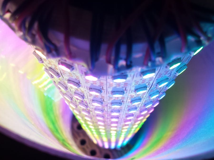
The LED strips are powered and grounded on one end. The data line goes from strip to strip. I have 4 strips on one fuse. With all the LEDs on it pulls about 2.9 amps for 4 strips.
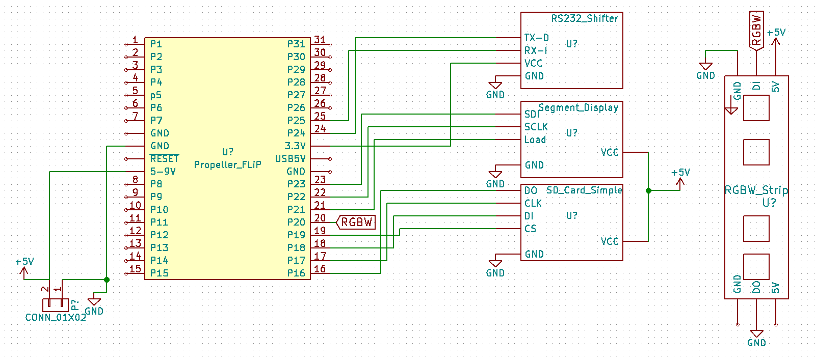
The Curr Step is just a display of the last step that worked. It gives me a basic idea where things broke. This is just a seven-segment display with 74hc595 shift register module from eBay.
(Add an image. Reorder images. Delete this image.)
I'm using a SparkFun board to do the rs232. It sits under the db9 board.
The serial port has the main debugging. I picked the board because of both gendered ports. I never know what cable I have when needing to debug.
I removed the screw terminals and made a cover with the communication information.
I'm using a standard SD card for animation and configurations storage.
For fusing of the RGB strip I'm using automotive fuses.
The processor is a Parallax Propeller on flip module.
I used a mean well power supply.
For AC connection, I sourced an IEC module with fuse and switch.
I mounted it to board to hold everything together.
The light tower is enclosed in a diffuser tube. It's about 5" in diameter.
It's a sheet held together with some aluminum bars. The bars were drilled and threaded with some sand paper attached to give some grip to the plastic.
The electronics are help in the base.
The enclosure as a whole is made to look like a column that would be found in a craftsman style of house.
The firmware is written in spin. Thanks goes out to the members of the parallax forums. Much of the driver code came from Jon McPhalen.

Comments