


Hardware components | ||||||
| × | 1 | ||||
| × | 1 | ||||
| × | 1 | ||||
| × | 1 | ||||
| × | 1 | ||||
| × | 1 | ||||
 |
| × | 1 | |||
Software apps and online services | ||||||
 |
| |||||
Content guidelinesIn a world where technology is transforming every aspect of society, healthcare cannot be left behind. The Intelligent Health Care Beacon emerges as an innovative solution specifically designed for remote areas, communities without medical coverage, expeditions, and other environments where access to healthcare services is limited. By integrating Artificial Intelligence (AI), the Internet of Medical Things (IoMT), robotics, and long-range communication networks such as LoRa, this system enables effective patient monitoring in places where hospital infrastructure is scarce or nonexistent.
What sets the Intelligent Health Care Beacon apart is its ability to combine various medical devices—from wearable sensors to autonomous robots—creating an intelligent ecosystem capable of collecting, analyzing, and transmitting vital information in real time. The Internet of Medical Things (IoMT) allows for the integration of wearable, implantable, and mobile monitoring stations, ensuring comprehensive health surveillance of the patient in any context.
Artificial intelligence enhances this system with advanced predictive analysis capabilities, detecting abnormal patterns in physiological data and generating early alerts that help prevent medical emergencies—especially in areas with limited access to healthcare professionals. This shortage of professionals is even more severe in rural or remote communities, which tend to be less appealing to new medical practitioners.
In such circumstances, AI and robotics play a fundamental role by offering practical solutions to these critical needs. It is important to emphasize that these technologies are not intended to replace medical personnel, but rather to complement them, significantly improving people’s quality of life.
The effective integration of various signal acquisition elements and different communication systems makes the Intelligent Health Care Beacon a particularly attractive and compelling tool for continuous monitoring and care of individuals.
Description of the Intelligent Health Care Beacon
The Intelligent Health Care Beacon incorporates sensors that measure heart rate, oxygen saturation, and systems for capturing cardiac signals and sounds using a digital stethoscope. It also includes a robotic arm capable of capturing heart sounds and recording respiratory sounds. This combination of technologies enhances healthcare personnel efficiency, reduces response times, and optimizes resource use in hard-to-reach scenarios.
This solution represents a significant advancement in the evolution of digital health, offering a holistic approach that democratizes medical care and extends its reach beyond traditional hospitals. With a robust, adaptable, and sustainable infrastructure, the Intelligent Health Care Beacon marks the beginning of a new era in smart medicine—where technology and healthcare merge to save lives anywhere in the world.
The Intelligent Health Care Beacon has been designed to operate efficiently in remote and challenging environments, ensuring optimal performance in real-time health monitoring and management. It is built with a shockproof and waterproof casing, effectively protecting all internal electronics. Thanks to the integration of Artificial Intelligence (AI), the Internet of Medical Things (IoMT), Robotics, and communication protocols such as LoRa, LTE, NB-IoT, WiFi, and Bluetooth BLE, the system enables accurate tracking of vital signs, early detection of anomalies, and real-time alert generation—even under limited connectivity conditions.
One of its greatest strengths is its ability to operate autonomously, reducing dependence on human intervention and enabling intelligent decision-making. Its sensor system collects patient data, which is then analyzed by AI to detect risk patterns. This allows healthcare personnel to receive preventive alerts, significantly improving emergency response capabilities.
In addition, the Intelligent Health Care Beacon prioritizes energy efficiency and operational autonomy. It supports LTE-M, NB-IoT, GNSS, and DECT NR+, and includes a dedicated antenna for LTE-M, NB-IoT, and DECT NR+ that supports a wide range of bands for global operation. The nRF9151 DK development kit offers the same coverage as the nRF9151 SiP module. Supported LTE bands include B1–B5, B8, B12, B13, B17–B20, B25, B26, B28, B65, B66, and B85. Additionally, its integration with LoRa enables long-distance data transmission with minimal energy consumption, making it ideal for deployment in rural areas, scientific expeditions, and environments with limited medical infrastructure.
Reliability and Operational EfficiencyIn terms of reliability, the Intelligent Health Care Beacon has been developed with data communication redundancy mechanisms and self-correcting algorithms that minimize errors and ensure accuracy in information transmission. Its modular architecture allows it to adapt to various scenarios, ensuring that the collected medical data is secure, consistent, and easily accessible.
However, like any technological system, its efficiency may be affected under extreme conditions, such as severe weather or environments with strong electromagnetic interference. To mitigate these challenges, the system implements local data collection and storage protocols, ensuring continuity of monitoring even when connectivity is intermittent.
Moreover, its highly automated design reduces the workload of medical personnel and minimizes the margin for human error in data collection and analysis. Compared to traditional monitoring methods, the Intelligent Health Care Beacon offers a faster, more accurate, and more accessible solution, positioning itself as an indispensable tool for digital health in remote areas.
System Overview
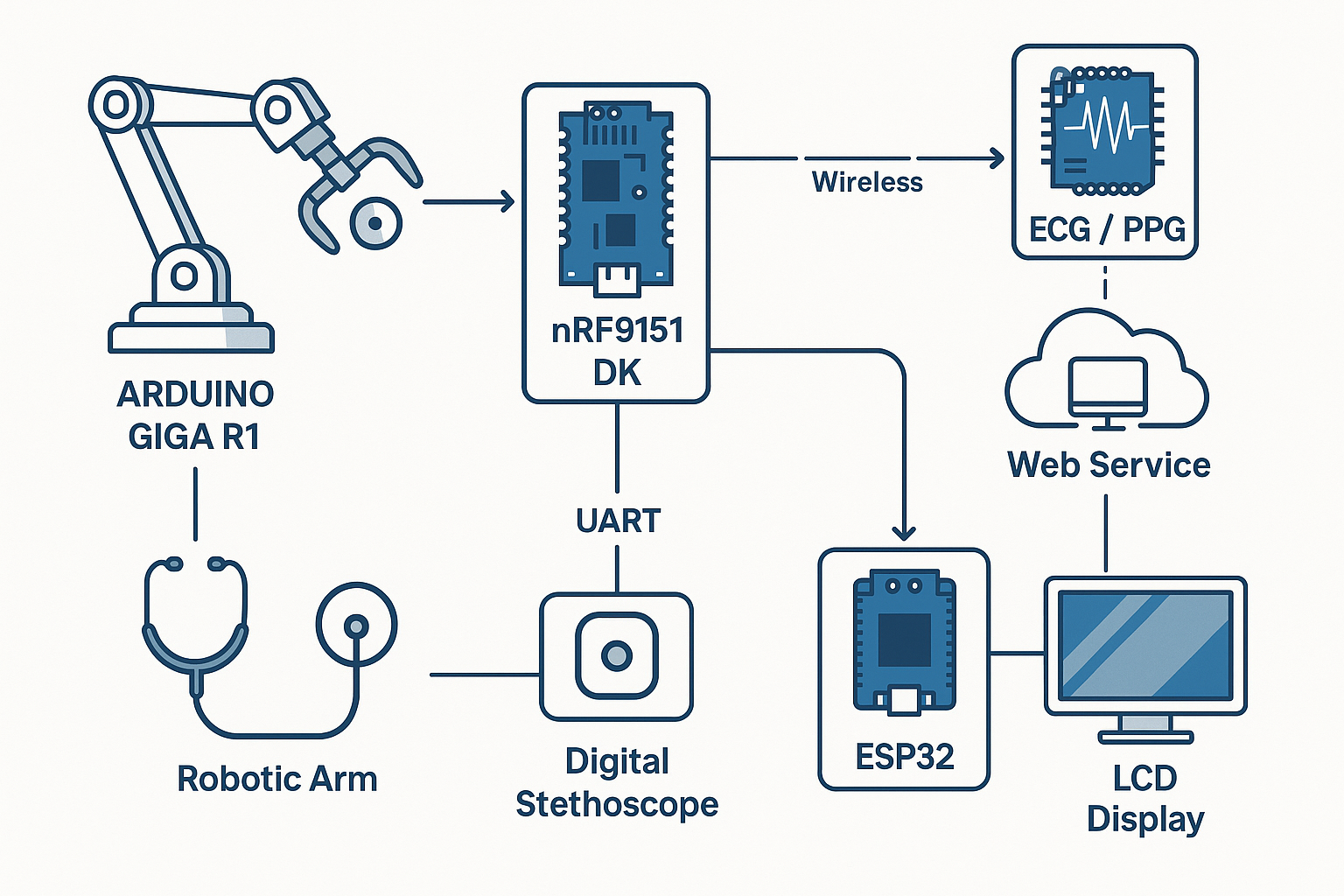
The system integrates several embedded platforms that operate in a distributed and coordinated manner:
- nRF9151 DK: Central node for biomedical signal acquisition (ECG, PPG, FCG), wireless communication (LTE-M, NB-IoT, LoRa), and GNSS positioning.
- Boron 404X Kit: Handles remote signal acquisition and bidirectional communication with a web server.
- Arduino GIGA: Controls a 5-DOF robotic arm and executes embedded machine learning models.
- ESP32-S3 7" LCD: Displays real-time signals and provides a user-friendly interface.
- Wio Terminal: Mounted on the robot end-effector to capture phonocardiographic signals.
The Intelligent Health Care Beacon has been designed using three main development systems: the nRF9151 DK, the Boron 404X Kit, and the Arduino Giga WiFi.
These three devices form the core of the semi-autonomous monitoring system. To complement and enhance this system, several additional devices have been integrated—not only improving the user experience but also contributing significantly to the overall development and functionality of the project.
Secondary ComponentsAmong these devices, the ESP32-S3 7-inch Display Development Board stands out, featuring a resolution of 800x480 pixels. It provides an intuitive and efficient visual interface for user interaction with the system.
In addition, the system includes a robot specifically designed for imitation learning, enabling it to observe and replicate human movements. This is particularly valuable in educational environments or in assisted tasks where remote or automated intervention is essential.
Due to the computational limitations of the hardware, and the inability to run complex machine learning models directly on the device, it was decided to use only the robotic arm, with its movements preprogrammed into the Arduino GIGA.
These movements allow the end effector to be positioned at specific locations, such as for capturing heart sounds using a stethoscope.
Given the complexity of the project—and considering that a single device would not be capable of fully managing the operation of the Intelligent Health Care Beacon system—it was decided to integrate the previously mentioned development platforms, distributing tasks more efficiently. This modular architecture enables better task distribution, improves the overall efficiency of the system, and facilitates scalability.
To allow internal communication between all modules, a message exchange protocol was developed based on serial communication between each of the devices (see Table 1).
Sensors
The Intelligent Health Care Beacon relies on a set of sensors for capturing various biosignals. Among these systems, the MAX30102 stands out—a heart rate and pulse oximeter sensor module based on the MAX30102 chip, which communicates via the I2C interface.
The MAX30102 is a complete system solution that simplifies the design of mobile and wearable devices. It integrates pulse oximetry and heart rate monitoring functionality into a single module, incorporating internal LEDs, photodetectors, optical elements, and low-noise electronics with ambient light rejection.
This sensor operates with a primary power supply of 1.8 V and an additional 3.3 V source for the LEDs. Communication with the microcontroller is carried out through a standard I²C interface. Additionally, the module can be powered down via software, with virtually zero standby current consumption, allowing the power lines to remain active at all times.
The system also includes the AD8232, a development module designed for capturing the heart’s electrical activity (ECG). This module uses a two-pole high-pass filter to remove motion artifacts and the electrode half-cell potential. Furthermore, it employs an uncommitted operational amplifier to implement a three-pole low-pass filter, which helps eliminate additional noise and improve signal quality.
The next component is the wireless digital stethoscope, which allows healthcare professionals to perform cardiopulmonary auscultations as usual—even while wearing protective isolation clothing—remaining completely separated from the patient.
In this way, it effectively prevents the risk of exposure to infections during the auscultation process, eliminating one of the main hazards associated with the use of traditional stethoscopes.
The BMD101 CardioChip offers revolutionary capabilities that enable wearable and mobile devices to easily capture health and fitness metrics directly from the user’s wrist or fingertips. These key metrics are extracted from ECG data processed by intelligent algorithms and are presented in a clear and accessible format, providing valuable insights into the user's health status and fitness level through wearable or mobile platforms.
Next are the LX-16A servos, which enable precise control of the robotic arm.
This servo delivers a high torque of 17 kg·cm (236 oz·in) at 7.4V and 15 kg·cm (208 oz·in) at 6.6V. It includes a communication protocol and detailed video tutorials to facilitate implementation. The servo provides real-time feedback on position, temperature, and voltage. Additionally, it features a warning light on top that flashes if any internal anomaly is detected.
It is built with all-metal gears, significantly improving precision and extending the device’s lifespan. The servo uses a dual ball bearing system—one for transmission and another as auxiliary support. It incorporates a high-precision potentiometer with an updated design, resulting in remarkable improvements in accuracy and linearity, making it ideal for the precise movements required in robotics.
The control board uses a single I/O port to connect servos in series via a dual-interface design, reducing the number of serial ports needed. This setup simplifies wiring, making the product more compact, streamlined, and user-friendly.
System Design and Architecture
The diagram presented illustrates the communication and processing architecture of the Intelligent Health Care Beacon.
Next is a detailed description of each subsystem that makes up the Intelligent Health Care Beacon system.
Bio-Boron 404X
The Bio-Boron 404X consists of a single main processing unit: the Boron 404X. This device forms the core of a portable system for capturing and transmitting biosignals such as ECG (electrocardiogram), PPG (photoplethysmography), and GSR (galvanic skin response).
The biosignal acquisition process begins with the BDM-101 sensor, which specializes in detecting ECG signals. The data is collected and processed locally, then transmitted by the Boron 404X to the cloud for storage or remote analysis, enabling real-time monitoring and decision-making.
The system uses a defined message structure for data transmission:
<DATA>:id=1;total=3;payload=12,34,45,94,...,45;<DATA>: Indicates that the message contains a portion of signal data.id: Represents the current segment number.total: Indicates how many segments make up the complete signal.payload: Contains the numerical data corresponding to that portion of the signal.
Since signals are captured over a period of 30 seconds, it is not possible to transmit the entire signal in a single message. Therefore, the information is split into multiple parts. The id and total fields allow the web server to reconstruct the signal in the correct order. The payload field includes the raw data corresponding to that specific segment of the signal.
In addition to data transmission, the Boron 404X enables bidirectional communication with a web server, allowing for remote management, real-time visualization, and system configuration through an intuitive web interface.
Similarly, the Bio-Boron 404X features an OLED LCD display, which allows for graphing the captured signals, and two touch buttons that let the user select the type of signal they want to capture. The Boron 404X handles the entire signal acquisition process. When the user selects a signal type—ECG, PPG, or GSR—the device initiates the capture of the specified signal and sends the data to the web server for processing and storage.
<REQ>:signal_type;The signal_type parameter is categorized into three types: ECG (electrocardiogram), PPG (photoplethysmography), and GSR (galvanic skin response). Once selected, the corresponding biosignal is captured by the system and transmitted to the web server, where it undergoes processing, analysis, and storage for further evaluation or integration into healthcare applications.
The web server will be explained in detail in the software description section.
Robot ControllThe robot is built using a modular design, making it easy to assemble, repair, and maintain, while keeping production costs low. It features five degrees of freedom and is primarily used for capturing heart sounds. However, its functionality can be extended to support other tasks.
The robot is controlled via an Arduino GIGA, which receives movement commands through the following instruction:
Message: <JOINT>:90,45,120,30,60

Joint Angles Representation:

      [Base]      [Shoulder]   [Elbow]     [Wrist 1]   [Wrist 2]
        90°           45°        120°         30°         60°
        │             │           │            │           │
        └── Joint 1 ──┴── Joint 2 ─┴── Joint 3 ─┴── Joint 4 ─┴── Joint 5
The robotic arm is mounted on a base platform, and the arm itself is removable, allowing for easy transport, maintenance, or replacement. The robotic arm is mounted on a base platform, and the arm itself is fully removable, allowing for easy assembly, transport, and maintenance. It is constructed using LX-16A smart servos, which are controlled via a serial communication protocol, enabling precise positioning of each joint.
The robot is operated through an LCD touchscreen interface, where the user can interactively select the target points that the end effector—equipped with a digital stethoscope—must reach. This design allows for accurate placement of the stethoscope on predefined anatomical locations, supporting reliable and repeatable acquisition of cardiopulmonary sounds.
At the end effector of the robot, a digital stethoscope is mounted. The robot's movements are guided based on the following mapping reference:
The heart sounds captured by the stethoscope are transmitted to the ESP32, where they are visualized on a display. These signals are recorded over a 30-second interval and temporarily stored in a buffer. Once the capture is complete, the data is sent using the structure defined in Table 1.
Secondary Stethoscope ModuleThe Wio Terminal, developed by Seeed Studio, is responsible for managing one of the two stethoscope modules and is mounted on the end effector of the robotic arm. This configuration enables precise positioning for targeted cardiopulmonary auscultation.
As an all-in-one embedded development platform, the Wio Terminal is powered by the ATSAMD51 microcontroller featuring a 120 MHz ARM Cortex-M4F core. It integrates a 2.4-inch LCD display, microphone, accelerometer, Wi-Fi/Bluetooth (via the Realtek RTL8720DN module), and multiple GPIOs, making it highly versatile for embedded sensing and IoT-based healthcare applications.
Within the system, the Wio Terminal captures phonocardiogram (FCG) signals using its onboard microphone and transmits the data via serial communication to an ESP32, where it is visualized in real time. Its compact design, onboard peripherals, and ease of integration make it a robust solution for portable biomedical signal acquisition..
By leveraging its onboard microphone and processing capabilities, the Wio Terminal captures phonocardiogram (FCG) signals during robotic auscultation. The robotic arm executes predefined movements to accurately position the stethoscope over specific anatomical landmarks, ensuring consistent and repeatable data acquisition.
Once acquired, the audio signals are transmitted via serial communication to an ESP32, where they are processed and visualized in real time on an LCD display. This setup enables non-invasive, interactive heart sound monitoring, making it especially valuable in applications requiring remote supervision or automated diagnostics.
At the core of the system is the nRF9151 DK, which serves as the central node for biomedical signal acquisition, communication, and coordination. This device is responsible for capturing a range of physiological signals, including:
- ECG (Electrocardiogram) – monitoring the electrical activity of the heart,
- PPG (Photoplethysmography) – assessing blood volume changes,
- FCG (Phonocardiogram) – detecting heart sounds through a digital stethoscope.
In addition to signal acquisition, the nRF9151 DK features advanced wireless communication capabilities, supporting protocols such as LTE-M, NB-IoT, and LoRa, which enable reliable data transmission even in remote or low-connectivity environments. The device also integrates a GNSS module for acquiring real-time geolocation data, which is useful for tracking the deployment of the system or enabling mobile health monitoring applications.
This central unit manages internal communication among all system components via UART interfaces, coordinating data flow and device interaction.
Dual Heart Sound Acquisition ArchitectureThe system is equipped with a dual heart sound acquisition setup to increase measurement reliability and flexibility:
- Robotic Arm + Wio Terminal One acquisition pathway uses a robotic arm to precisely position a Wio Terminal equipped with an onboard microphone. This configuration enables targeted cardiopulmonary auscultation. The Wio Terminal transmits the captured heart sounds to an ESP32 module via serial communication, where the data is plotted in real time on an LCD display.
- Digital Stethoscope + nRF9151 DK The second pathway employs a digital stethoscope directly connected to the nRF9151 DK, enabling simultaneous and redundant acquisition of heart sounds for enhanced robustness.
Once the biomedical signals are processed, the data is distributed to two main subsystems:
- An LCD display, responsible for providing real-time visualization of the acquired biomedical measurements.
- An Arduino GIGA, which controls the robotic arm and executes machine learning models. These models leverage the processed signals (especially ECG) to perform advanced analytics and make autonomous decisions during operation.
This modular and distributed architecture ensures robust, flexible, and scalable acquisition, processing, and visualization of biosignals. The system is designed to operate reliably even in resource-constrained environments, making it suitable for mobile, remote, or low-connectivity healthcare applications.
When the system receives biomedical data such as ECG, PPG, or temperature readings, it acknowledges the reception with the following command:
<ACK>:DATA_RECEIVED;This response is followed by a structured serial interface that simulates a basic user form on a display (such as an LCD connected to an ESP32), allowing healthcare operators to input or review patient data. The interface includes labeled fields for patient information, such as name, age, weight, blood sugar level, blood pressure, and sex.
The interface may also include on-screen buttons to interact with the system, such as saving the entered data or closing a virtual keyboard.
Translated Interface Layout<ACK>:DATA_RECEIVED;
+------------------------------------------------+
| Serial Display |
| |
| [> ECG Initialized] |
| |
| -------------- Patient Form ------------------ |
| Name: [__________] |
| Age: [__________] |
| Weight: [__________] |
| Sugar: [__________] |
| Pressure: [__________] |
| Sex: [__________] |
+------------------------------------------------+
+-----------------------------+ +----------------------+
| Name: [___________] | | [Close Keyboard] |
| Age: [___________] | | [Save Data] |
| Weight: [___________] | | |
| Sugar: [___________] | | |
| Pressure:[___________] | | |
| Sex: [___________] | | |
+-----------------------------+ +----------------------+This layout simulates a real-time user interface for interacting with the data acquisition system, commonly displayed on an embedded LCD (e.g., 7-inch ESP32-S3 screen). It enables interactive entry or confirmation of patient data, enhancing usability in mobile or field healthcare applications.
Would you like this turned into a graphical mock-up or used in the Hackster documentation as a sample interface section?
Atrial Fibrillation DetectionCardiovascular diseases (CVDs)—such as hypertension, ischemic heart disease, and arrhythmias—are currently the leading cause of death worldwide.Monitoring the ECG signal is a key aspect of cardiovascular healthcare, as many CVDs can be more effectively diagnosed, managed, and prevented through continuous monitoring systems.
Recent advancements have focused on integrating new technologies into ECG monitoring solutions to make them more efficient, cost-effective, connected, and energy-efficient. In this section, we present the most relevant and related work in the field, emphasizing their contributions to the state of the art.
Here is the rewritten version in polished English, suitable for academic or technical contexts:
Cardiac arrhythmias are among the most frequently treated conditions by clinical cardiologists. Atrial fibrillation (AF)is the most common heart rhythm disorder in the general population, and its incidence and prevalence are steadily increasing worldwide—particularly in developed countries.
In Europe, for example, it is estimated that 1% to 3% of the adult population is diagnosed with AF, with the rate exceeding 15% among individuals aged 80 and older.
While a normal sinus rhythm appears as a single, organized wavefront propagating from the atria to the ventricles, AF is marked by multiple erratic wavefronts with varying propagation patterns. These irregularities can be asymptomatic or lead to symptoms such as palpitations, shortness of breath (dyspnea), and dizziness.
To address this, the robot incorporates a model capable of classifying ECG signals, enabling early detection and more accurate monitoring of atrial fibrillation.
- Nr - Normal sinus rhythm
- Af - Atrial fibrillation
- O - Other rhythm
- No - Too noisy to classify
In order for the robot to perform ECG signal classification, the user must have access to an ECG capture device.
The electrocardiogram (ECG) is a common diagnostic test used to detect cardiac abnormalities and monitor heart health. It provides a graphical representation of the heart's electrical activity, recorded through electrodes placed on the body surface.
The standard ECG includes 12 leads that capture the electrical potentials of the heart from different angles:Lead I, Lead II, Lead III, aVR, aVL, aVF, V1, V2, V3, V4, V5, and V6.
To achieve this classification, a correctly labeled signal dataset is required. The dataset used for this project was used in a cardiology challenge in 2017 on the Physionet website. There are different ways to approach this classification problem, in my case I have chosen to convert each of the signals present in the database into an image.
This process resembles the methodology that a physician uses when reading an ECG, he does not analyze the signal by performing possible frequency transformations and using advanced signal processing techniques. In his case, the physician uses the ECG signal printouts and analyzes the signal, based on his academic training. In this way, he can determine if the distance between R peaks is too high or too low or if any of the other waves are abnormal (Figure 23).
During the realization of this project, I tried different ways to use the signal (which in my opinion is the best option), but I tried to get the computer to read a sequential network but I did not get any results.
The training of the network that anonymizes the ECG signals resulted in the classification scores presented in Table 3. As can be seen in the table and in the confounding matrix (Figure 28), the classification percentage was satisfactory and a precision of 93% was obtained.
The Intelligent Health Care Beacon represents a significant advancement in the field of remote and intelligent health monitoring. By integrating ECG signal analysis, AI-driven classification models, and real-time connectivity, it offers a robust solution for early detection and prevention of cardiovascular conditions such as atrial fibrillation. Its modular and autonomous design ensures adaptability to various environments, from urban to rural or expeditionary settings, enabling continuous patient monitoring even under limited infrastructure.
Moreover, the system enhances healthcare delivery by reducing response times, supporting medical professionals, and minimizing human error—making it a valuable asset in the global effort to democratize access to healthcare.
Image Gallery


Comments