


Hardware components | ||||||
 |
| × | 1 | |||
 |
| × | 1 | |||
 |
| × | 1 | |||
| × | 1 | ||||
| × | 1 | ||||
Software apps and online services | ||||||
 |
| |||||
| ||||||
Hand tools and fabrication machines | ||||||
 |
| |||||
 |
| |||||
 |
| |||||
Do you have that one button or switch in your house that is always so annoying to (de)activate? Well, then the Helping Finger project might just be the perfect solution to your problem.
Whether it's the light switch you want to turn off from your bed, the coffee maker you want to add to your morning routine, the projector on your ceiling that's hard to reach, the computer you want to start a few minutes before you get home. No matter what switch or button it is, the Helping Finger will be able to turn your device off and on whenever you want and from wherever you want. The Helping Finger can be controlled via a Android App, Amazon Alexa, Google Home, IFTTT, a iOS App and Samsungs Smart Things.
Pre-informations:To accomplish this, we need a few things listed in the "Things" category. The ESP8266 board will act as the heart of the project, from which everything will be controlled. The chosen WeMos D1 Mini turns out to be very small, but offers enough connections in the process. This WeMos D1 Mini has a WLAN chip, which allows it to set up a local network, as well as to connect to a WLAN router and connect to the World Wide Web.
ESP8266 describes a cheap WLAN module, which can control inputs and outputs. The ESP8266 module is available in various versions, This project was successfully implemented with the ESP8266-12E NodeMCU Kit version as well as the WeMos D1 Mini version. The following instructions focus on the implementation using the WeMos D1 Mini, in the following referred to as D1 Mini. Further information about ESP8266 can be found here.
The pins of the D1 Mini are used to operate the servo motor, which will actuate your switch or button after completion of the project.
It is important to remember that a servo motor that is continuously powered has a high power consumption and cannot be moved.
Accordingly, depending on the application, it may be worthwhile to include a relay, this disconnects the power supply to the servo motor when not in use, making the servo motor movable. This is recommended, among other things, for light switches, as otherwise manual operation may no longer be possible.
How to build a Helping Finger:To build the Helping Finger the following steps are necessary:1. Get the D1 Mini running2. The code3. Connect the servo motor4. Print the casing5. Assemble of all parts
1. Get the D1 Mini running
The first part of the project is the programming of the ESP8266 board. If not already done, it may be necessary to install the drivers of the board.If the D1 Mini board is used, the driver for Windows and Mac can be found here.
Afterwards you can connect your D1 Mini to the computer via a micro-USB cable.
Then you need to prepare your Arduino IDE for the D1 Mini. A good tutorial on how to this, can be found under this link. It is important to add the ESP8266-Kit to the board-manager in the File>Preferences and after that you need to install the ESP8266 package in the Tools>Board>Board Manager.
To upload a code to your board you need to select the D1 Mini in Tools>Board>LOLIN(Wemos) D1 R2 & Mini. Also you need to select the right port in Tools>Port. In case you are unsure, which port your D1 Mini is connected to, you open your Device Manager and find it in the port category.
After this you can upload an example code onto your D1 Mini. For testing you could try this code:
/*********
  Jannis Kartenberg
  Complete project details at:
  https://www.hackster.io/jannis-kartenberg/helping-finger-b5047f
*********/

void setup() {
  pinMode(LED_BUILTIN, OUTPUT);
}

void loop() {
  digitalWrite(LED_BUILTIN, LOW);
  delay(1000);
  digitalWrite(LED_BUILTIN, HIGH);
  delay(1000);
}
This code should make your Buildin LED on the board blink with a frequency of 0, 5Hz. If this is happening, you are ready for step 2 of the build process.
2. The code
The code to control the board via Smart Home can be downloaded here. Depending on which Smart Home device you want to use, there are different versions of the code, there is one code version for an Android App, Alexa, Google Home, IFTTT, iOS App and Samsung Smart Things and one code version for the Apple Homekit implementation. There is also a code version for a native implementation into Amazon Alexa, but during testing there were found some issues which make the implementation a bit difficult. The goal for the future will be to combine both code variants into one.
Android App, Alexa, Google Home, IFTTT,iOS App, Smart Things:
To realize this different ways listed above of contorolling your device the service "Sinric Pro" is used.
First you need to create a Sinric Pro account via http://portal.sinric.pro/register. Then you need to create your device in Sinric Pro. To do this, you need to follow the following steps:
1. Login to your Sinric Account 2. Go to the Devices menu on the left3. Click the Add Device button on the top left4. Enter a device name, a description of your choice5. Select the device type as Switch6. Select the Room where the device will be located7. Select the Device Access Key. This will be added later in the code.8. Click Save
As a next step you can connect the applications you want to use.
- The Apps for Android and iOS can be found in the dedicated app stores under the name "Sinric Pro"
- For your Alexa you need to add the Alexa Smart Home Skill "Sinric Pro"
- For Samsung Smart Things good instructions can be found here
- For Google Home a Samsung Smart Things connection is necessary, since Google doesn't allow a native implementation of Smart Home Devices. Instructions on how to implement your device in Google Home can be found here
- Instructions on how to implement your device via IFTTT can be found here
After including Sinric Pro into your Smart Home, we need to connect the board to Sinric Pro. For this step you need to download the "Sinric and Servo" folder from the Github repository.
After downloading and unzipping the folder, you can open the "Sinric_und_Servo.ino" file. In the top you will find the libraries which are necessary for the project. Below this you will find the define area, where you need to include your informations, delivered by Sinric Pro. To find this informations follow these steps:
1. Login to your Sinric Account 2. Go to the Credentials menu on the left3. Copy the App Key and the App Secret into the code4. Go to the Devices menu on the left5. Copy the Device-ID into the code
Now open the Serial Monitor in the Arduino IDE via Tools>Serial Monitor and upload the code to your board. In case your upload was successful you could try turning it off and on via your selected connection method. A successul connection should look like this:
Apple Homekit
Unfortunately Sinric Pro doesn't support Apple Homekit yet, but there is another way of connection possible. Since I don't own Apple products my experience rely on a few moments of testing the following code with a friends phone. The necessary code can be found in the "mein_schalter" folder from the Github repository. The original code including instructions on how to connect the D1 Mini with Apple Homekit can be found here.
3. Connect the servo motor
As a servomotor a standard SG90 motor is used. Important for us is the wire colouring, which can be found in the data sheet.
To connect the servomotor with the board, the pinout from the D1 Mini is necessary.
In case you want to control your switch with the Helping Finger alone, or it is a button, you can connect your servo motor directly to your D1 Mini. So you connect the Orange cable to the Pin given in your Code. On the D1 Mini all pins are able to send out a PWM signal.The brown cable will be connected to the GND pin of the D1 Mini and the red cable will be connected to the 5V pin of the D1 Mini.In case you still want to be able to control your switch manually, you will need to turn off the servo motor in times, when it is not needed. In this case you have to add a relais into the power circuit of the servo motor, so either in the 5v or the GND connection.
To test the connection, you can use the "Servo" folder from the linked github.
4. Print the casing
Now all things need to be boxed up. As a casing I decided for a 3D-printed casing, which can be found in the "Custom parts and enclosures" part of this page. Depending on your location, where you want to install your Helping Finger, you can modify the.stl file to your wishes.
In the.stl file also included is an enlargment for the rotor of the servomotor.
For mounting the housing later I recommend double-sided adhesive tape. However, you should not fix this before everything is adjusted correctly.
5. Assemble of all parts
Now that all parts are ready, we can assemble everything.
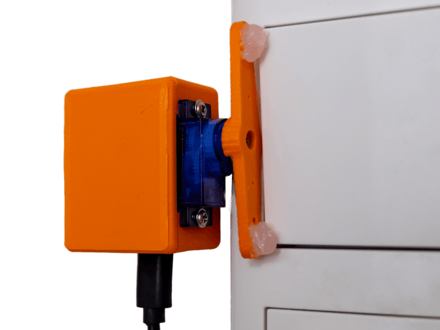
First you should solder the wires of the servomotor and the optional relais onto the D1 Mini board.After that you can place the D1 Mini on the bottom of your casing. Then align the board with the whole for the USB cable. Afterwards you can attach the board to the casing with some second glue or hot glue. Then position the relais on the opposit site of the big hole in the caing. And as a final step mount the servo motor with the included screws to the casing and screw the rotor with or without the extension onto the servo motor.
It will look something like this:
Flashing problems occurred during testing. These were probably caused by voltage dips, which can be traced back to the coil of the relay. As a short-term solution, a capacitor was installed. However, this should not be necessary as long as the relay is not switched during flashing.
How to Use:As soon as the setup is connected to power, the board will try to get a WiFi connection, with any of the already known networks. If this is unsuccessful (or no previous network was saved) the ESP changes into Access Point mode and creates a local network including a WebServer (default ip 192.168.4.1). Now you have to connect to the local network created by the D1 Mini with any wifi enabled device. The website of the WebServer should autmatically open up. A list with all networks in the area will be shown. Click on the network you want to connect to, enter the password and click save. The D1 Mini will close the Access Point and try to connect to the saved network.
If the connection is successful the connection to Sinric Pro will be established. If this connection is successful, you will be able to control your device with any type of application that you setup.
In the following video, the light switch is controlled via the Sinric Pro Android App, Samsung Smart Things, Alexa, Google Assistant and Google Home.
CostsThe costs for the project are listed below:
- D1 Mini ~6€ p.p.
- SG90 servomotor ~3€ p.p
- relais (if necessary) ~1, 3€ p.p
- USB-cable ~2€ p.p
- USB-charger ~5€ p.p
- casing (19 gram à ~18€ per kilo = 30ct)
total: ~15-20€


Comments