


Hardware components | ||||||
 |
| × | 1 | |||
 |
| × | 1 | |||
Software apps and online services | ||||||
| ||||||
Hand tools and fabrication machines | ||||||
| ||||||
 |
| |||||
WORK IN PROGRESS!!
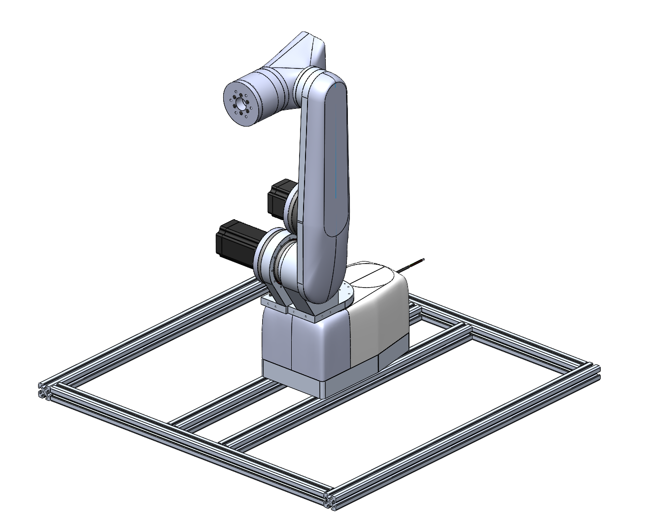
AboutIRAS is my self-made robot arm, designed to have a large work envelope and high carrying capacity. With IRAS I compete at Jugend-Forscht, a German science competition. Many parts are made from machined aluminium and 3d-printed.
IRAS is used to do research regarding intuitive control of industrial robotic arms. IRAS won’t be a stand alone robot arm but rather a system of the IRAS arm itself and many accessories for easy and intuitive control. However the foundation for my research is a capable robotic arm.
This robot arm is the second one I build, with the old one beeing fully 3d-printed, but still fairly large. With IRAS I want to achieve a carrying capacity of over 8kg with a work envelope exceeding 1 metre and a sub millimetre repeatability.
The precision and strenght is achieved by aluminium parts machined by JLCCNC.
Special thanks to JLCCNC, who machined those great looking parts, as well as Nabtesco, who support this project too.
(Disclaimer: This project is still in an early stage, and files aren’t accessible yet. The competition will be in the first quarter of 2026. This webiste will be constantly updated, as soon as new content is available)
More infos can be found on my website: jacobutermoehlen.com/projects/iras
1. How I assembled the first three joints for maximum rigidity:
I obted for a shrink fit between the bearings and the bearing housing annd rotating shaft as this will guaranty highest precision and rigidity without using a crossed roller bearing.
For this to work I heated up the bearings inner races and housings and cooled the other parts. Because of this and of the tight tolerances the parts had I then could assemble the parts easily and the joint assemblies will be super rigid.
2. Belt driven third joint:
Currently I joint three is belt drive. However I have to test how well this works and eventually skip the belt and make it directly driven, which would be that complicated to change afterwards.
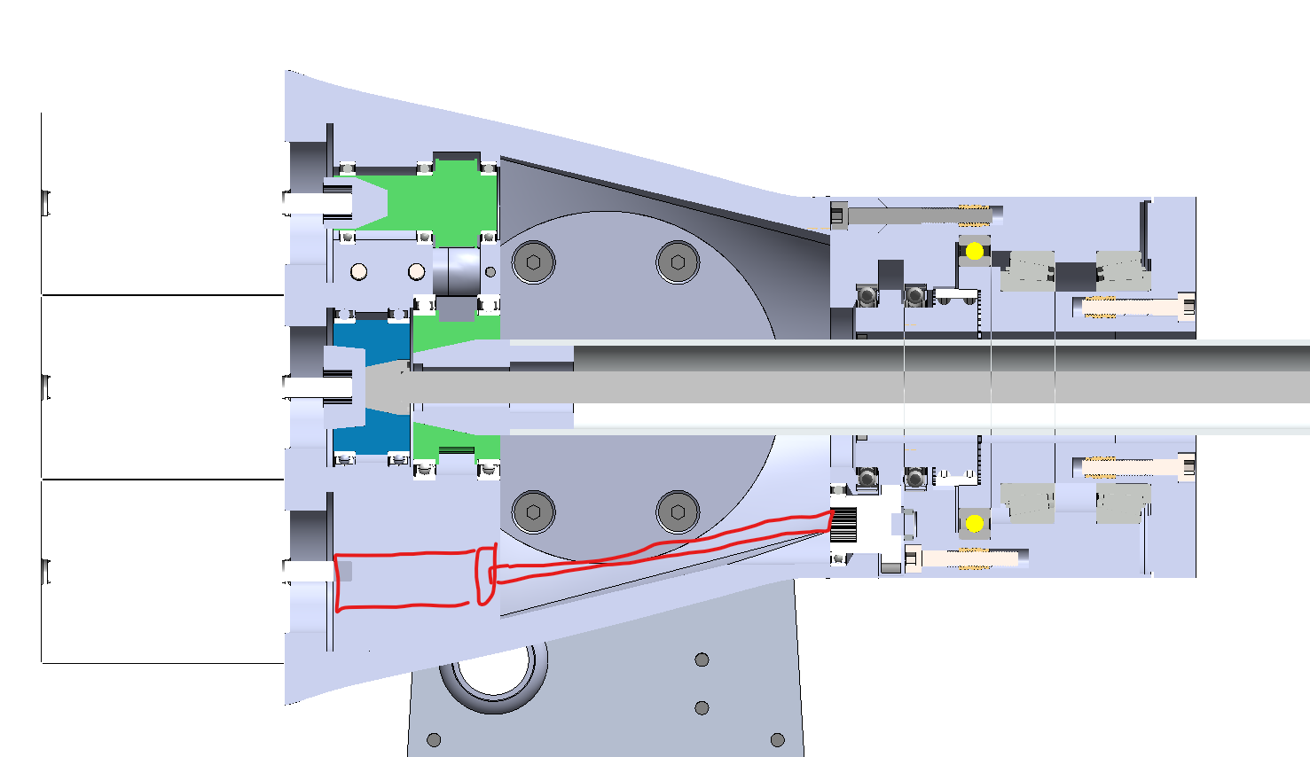
3. Development of Joint 6th cycloidal gearbox
Eventhough I use industrial grade harmonic drives for the first three joints, I dont use off the shelf ones, because I wanted to keep cost down and also have more design freedom.
In the past I have already designed gearboxes for my first robotic arm, though they were fully 3d-printed and lacked precision and strength. For the design of the 6th gearbox I focused on:
- as little backlash as possible
- high torque
- torsional stiffness
- high bearing loads
- compactness
My first design (first image) was neither capable of high torque nor designed for high torsional stifness.
The area circled in blue is the major weakpoint of this iteration. The pins responsible for driving the output are only press fitted 5mm into the material and during test often bent the hole, especially as they had to be relatively thin and long.
(My test were conducted with plastic parts, though simulation have shown, that even in aluminium the hole would deform reasily under high load.)
This this design is therefore not suitable for high loads and good stiffness. The red area is wasted space, which I tried to eliminate in the 2nd iteration.
Promising seemed to be my 2nd version, eventhough its called the predecessor, the design is nowhere close to the first. The make the assembly more compact, I moved the mechanism between the two tapered roller bearings, this way the otherwise wasted space (like in V1) is beeing used effectively.
Also the output driving pins, can no longer twist as easily, as they are supported from the back and also screw into the output which decreases bending.
After I have finilized my design with more than 10 prototypes, I let JLCCNC machine the critical parts for me from aluminium 6061 and 7075. JLCCNC did a great job and through their help and precise machining the final gearbox has zero backlash and a high rigidity.


Comments