


Hardware components | ||||||
 |
| × | 2 | |||
Hand tools and fabrication machines | ||||||
 |
| |||||
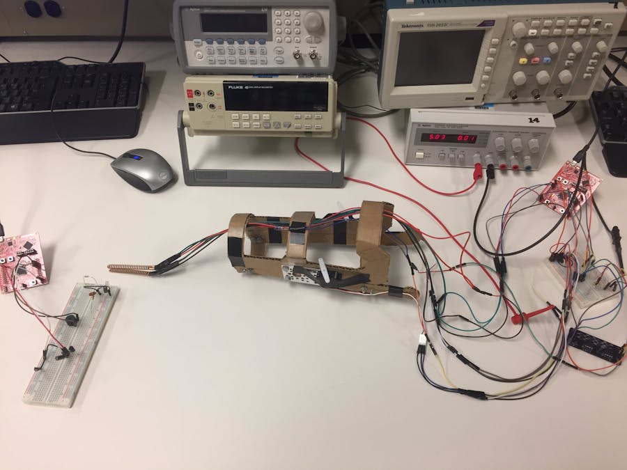
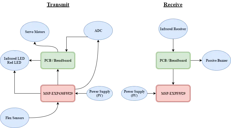
For my final Embedded Systems class project, I wanted to explore an interest to mine since I decided to pursue a degree of engineering. I chose to build a laser tag system that would be housed inside a mechanical gauntlet. I have always been fascinated with robotics and laser technology. I felt this project would be a fun but informative learning experience for controlling servo motors and LEDs. I wanted to incorporate flex sensors, servo motors, and an infrared LED that would trigger a corresponding infrared receiver at a frequency of 40 KHz. Once the receiver, or target, received the signal, it would output to a speaker signifying the “hit”. I used two MSP-EXP430F5529 Launchpads. My only prior experience going into this project was with servo motors and some Analog-to-Digital Conversion (ADC). Thus, the goal of this project was to incorporate ADC, servo motor control, LEDs, and speakers.
��x��/
Transmit Code for Infrared LED
C/C++//This program is the transmission portion of Jackson Love's final project.
//The program will read in a analog voltage from two flex sensors
//and control an infrared LED and two servo motors based on the threshold values.
//This program uses a motor driver to step up the current to operate the infrared LED.
#include <msp430.h>
#define Motor BIT2 //P1.2 is designated for the two motors
#define RedLED BIT4 // P1.4 designated for the test LED
#define InfLED BIT3 // P1.3 for the infrared LED
#define Button BIT1
#define Flex1 BIT0
#define Flex2 BIT1
volatile unsigned int ADCresults[2];
const float VCC = 5.08; // 5V pin
const float R1_Divisor = 46120; //Flex sensor 1 divisor
const float R2_Divisor = 46520; //Flex sensor 2 divisor
const float R1StraightResistance = 28190; //Flex sensor 1 straight resistance
const float R2StraightResistance = 30770; //Flex sensor 2 straight resistance
const float R1BendResistance = 120000; //Max resistance value for R1
const float R2BendResistance = 125000; //Max resistance value for R2
int Angle = 1500; //initial position.
int degree90 = 1600; //90 degrees. Neutral position
int degree45 = 2200;//45 degrees. Position 1
int motorOn = 1;//variable that tracks whether motor is on or off
int state = 0; //state machine variable that tells if at position 0 or 1
//position 0: neutral
//position 1: rotates right
void main(void)
{
WDTCTL = WDTPW+WDTHOLD; // Stop watchdog timer
P6SEL = Flex1 + Flex2; // Enable A/D channel inputs
ADC12CTL0 = ADC12ON+ADC12MSC+ADC12SHT0_2; // Turn on ADC12, set sampling time
ADC12CTL1 = ADC12SHP+ADC12CONSEQ_1; // Use sampling timer, single sequence
ADC12MCTL0 = ADC12INCH_0; // ref+=AVcc, channel = A0
ADC12MCTL1 = ADC12INCH_1; // ref+=AVcc, channel = A1
ADC12MCTL2 = ADC12INCH_2; // ref+=AVcc, channel = A2
ADC12MCTL3 = ADC12INCH_3+ADC12EOS; // ref+=AVcc, channel = A3, end seq.
ADC12CTL0 |= ADC12ENC; // Enable conversions
WDTCTL = WDTPW + WDTHOLD; // Stop watchdog timer
P1DIR |= BIT2 + RedLED+ InfLED; //Motors, Red LED, and Infrared set as outputs
P2REN |= Button;
P2OUT |= Button;
P1REN |= Button; // enable pull-up resistor for switch
P1OUT |= Button; // enable pull-up resistor for S2 (P1.3)
P1IE = Button; // enable P1.3 interrupt
P1IES= Button;
P1IFG = 0x00; // clears interrupt flag
TA0CCTL0 = CCIE; // CCR0 interrupt enabled
TA0CCR0 = 5000; // Set count threshold
TA0CTL = TASSEL_1 + MC_0; // SMCLK, up mode (starts timer!)
TA1CCTL0 = CCIE; // CCR0 interrupt enabled
TA1CCR0 = 1500; // Set count threshold
TA1CTL = TASSEL_2 + MC_1; // SMCLK, up mode (starts timer!)
__enable_interrupt(); // enables selected interupts
while(1) // infinitely loop
{
ADC12CTL0 |= ADC12SC; //begins ADC sampling conversion
ADCresults[1]= ADC12MEM1; //assigns results buffer to memory 1
ADCresults[0] = ADC12MEM0; //assigns results buffer to memory 1
if(ADCresults[1] < 2500) // if flex sensor 1 analog reading is less than 2500
{
P1OUT ^= RedLED; //turn on the Red LED as long as sensor is bent
P1OUT ^= InfLED; //turn on the infrared LED as long as sensor is bent
}
else
{
P1OUT &= ~InfLED; //turns off the red LED
P1OUT &= ~RedLED; //turns off the infrared LED
}
if (ADCresults[0] < 2500) // if flex sensor 2 analog reading is less than 2500
{
Angle = degree45;//move motor to angle of 90
state = 1;//change state
}
else
{
Angle = degree90;//rotate motor 45 degrees
}
}
}
#pragma vector=TIMER1_A0_VECTOR
__interrupt void Timer_A1 (void) // Timer A0 interrupt service routine
{ // the TACCR0 CCIFG flag is automatically reset
if (motorOn == 1)//statement for motor on
{
P1OUT |= BIT2;//sets P1.2 as output, turns motor on
TA1CCR0 = Angle; // Sets max counter to Angle
motorOn = 0;//set to 0 for motor off state
}
else
{
motorOn = 1;
P1OUT &= ~BIT2; //turns motor off
TA1CCR0 = 20000;//delay for 20 millisecond
}
}
//code from ADC example
//reads the analog values and assigns them to the results buffer
#if defined(__TI_COMPILER_VERSION__) || defined(__IAR_SYSTEMS_ICC__)
#pragma vector=ADC12_VECTOR
__interrupt void ADC12ISR (void)
#elif defined(__GNUC__)
void __attribute__ ((interrupt(ADC12_VECTOR))) ADC12ISR (void)
#else
#error Compiler not supported!
#endif
{
switch(__even_in_range(ADC12IV,34))
{
case 0: break; // Vector 0: No interrupt
case 2: break; // Vector 2: ADC overflow
case 4: break; // Vector 4: ADC timing overflow
case 6: break; // Vector 6: ADC12IFG0
case 8: break; // Vector 8: ADC12IFG1
case 10: break; // Vector 10: ADC12IFG2
case 12: // Vector 12: ADC12IFG3
ADCresults[0] = ADC12MEM0; // Move results, IFG is cleared
ADCresults[1] = ADC12MEM1; // Move results, IFG is cleared
case 14: break; // Vector 14: ADC12IFG4
case 16: break; // Vector 16: ADC12IFG5
case 18: break; // Vector 18: ADC12IFG6
case 20: break; // Vector 20: ADC12IFG7
case 22: break; // Vector 22: ADC12IFG8
case 24: break; // Vector 24: ADC12IFG9
case 26: break; // Vector 26: ADC12IFG10
case 28: break; // Vector 28: ADC12IFG11
case 30: break; // Vector 30: ADC12IFG12
case 32: break; // Vector 32: ADC12IFG13
case 34: break; // Vector 34: ADC12IFG14
default: break;
}
}
#include  <msp430.h>
#define RedLED BIT0
#define GreenLED BIT6
#define Button BIT3 // output of infrared receiver
#define SPEAKERLOW BIT4 //negative piezzo
#define SPEAKERHIGH BIT5 //positive piezzo
int enableBuzzer = 0;
void playNote(unsigned char pitch);
void playNoteForDuration(unsigned char pitch, unsigned char duration);

void main(void) {
	WDTCTL = WDTPW + WDTHOLD;       // Stop watchdog timer
	P1DIR |= SPEAKERLOW | SPEAKERHIGH;		//sets the two LEDs to output
	P1REN |= Button;
	P1IE = Button;	//enable interrupt for Button
	P1IES = Button;	//initializes the interrupt on the clock edge select
	P1OUT |= Button;			//sets Button as an output
	TA0CCR0 = 3000;              // Upper limit of 3000 cycles
	TA0CCTL0 = CCIE;             // enable the interrupts from TimerA0 CC0
	_enable_interrupts();
//note that TACTL is not initialized. It will be called in the PORT1 interrupt

	while (1)
	{
		if (enableBuzzer==1)
		{

 			playNoteForDuration('c',1);
			enableBuzzer=0;
			P1IE = Button;
		}
	}
}
#pragma vector = TIMER0_A0_VECTOR	//timer interrupt
__interrupt void TA0_ISR(void)
{


		enableBuzzer = 1;	//toggles the Green LED

		TA0CTL = MC_0;//then sets the control to MC_0 to stop counting
}
//if the Button is pressed, PORT1 interrupt starts
//normally, TACTL is MC_0, so this interrupt sets TACTL to MC_1
//if the button is pressed, Timer A will begin counting up to 3000
//This way the timer is only started when the button is pressed
#pragma vector = PORT1_VECTOR
__interrupt void PORT1_ISR(void)
{
	if (!(TA0CTL & MC_1)){	//if Timer A control is not set to MC_1
		TA0CTL = TASSEL_2|MC_1|ID_2|TACLR;	//sets TACTL is set to MC_1
		P1IFG = 0;	//clears flag
	}
	P1IE &= ~Button;
	P1IFG = 0;	//clears flag
}

void playNote(unsigned char pitch) //Function to play the array of notes
{
    P1OUT &= ~SPEAKERLOW;   //grounds the speaker
    P1OUT |= SPEAKERHIGH; //Speaker will constantly be changing therefore creating a sound
    int P;  //local variable for Pitch
    int L = 15000;  //sets the length of the note to be played
    int j;
    int i;
    int h;
    switch (pitch) // note that the frequency to loop ratio is 28923.8/Hz = loop number
    {//a range of 7 notes are used in this array
    case ('c'):  //middle c note in the 4th octave
        P = 360;  //calculated frequency for c
        L = L / P; //This gives each note a common time. Syncs with the chip clock
        break;
    case ('d'):  //d note in the 4th octave
        P = 232;
        L = L / P;
        break;
    case ('e'):  //e note in the 4th octave
        P = 206;
        L = L / P;
        break;
    case ('f'):  //f note in the 4th octave
        P = 195;
        L = L / P;
        break;
    case ('g'):  //g note in the 4th octave
        P = 174;
        L = L / P;
        break;
    case ('a'):  //a note in the 4th octave
        P = 155;
        L = L / P;
        break;
    case ('b'):  //b note below middle c (3rd octave)
        P = 276;
        L = L / P;
        break;
    case ('C'):  //c note in the 5th octave
        P = 130;
        L = L / P;
        break;
    case ('r'):  //rest case. This allows a musical break in between notes
        P = 0;
        L = L / 4;  //specifically catered to be a different loop cycle
        break;
    default:
        P = 0;
    }
    for (h = 5; h > 0; h--) { //multiplies the Length (L) to a play at a longer duration
        for (j = L; j > 0; j--)  //sets j = L (15000) to loop 15000 times
                {
            if (P != 0) //when P =0, there is not a set frequency, but is inaudible to hear
                    { //by setting P not to 0, this will read the rest case as a pause, not a frequency
                P1OUT ^= SPEAKERLOW;    //speakers will play a frequency.
                P1OUT ^= SPEAKERHIGH;
            }
            for (i = P; i > 0; i--)
                ; //P set to an integer to keep the frequency everytime. Otherwise P will be 0 constantly as it cycles
        }
    }
}

void playNoteForDuration(unsigned char pitch, unsigned char duration) //Duration function for playing the note
{ //this function will multiply the length of the note in playNote function for a duration multiplier set in the array
    int i;    //sets i = duration intitially
    for (i = duration; i > 0; i--)
        playNote(pitch); //passes in pitch as it cycles through the array
}


Comments