


Hardware components | ||||||
| × | 1 | ||||
| × | 1 | ||||
| × | 1 | ||||
| × | 1 | ||||
| × | 1 | ||||
 |
| × | 1 | |||
 |
| × | 35 | |||
 |
| × | 1 | |||
 |
| × | 2 | |||
 |
| × | 2 | |||
Software apps and online services | ||||||
 |
| |||||
Hand tools and fabrication machines | ||||||
 |
| |||||
 |
| |||||
 |
| |||||
 |
| |||||
 |
| |||||
Smart devices are everywhere - in your home, your pocket, your wrist, even your glasses; the next frontier is clothing, and many companies including Google are tackling this challenge. We are happy to put in our own efforts into the race.
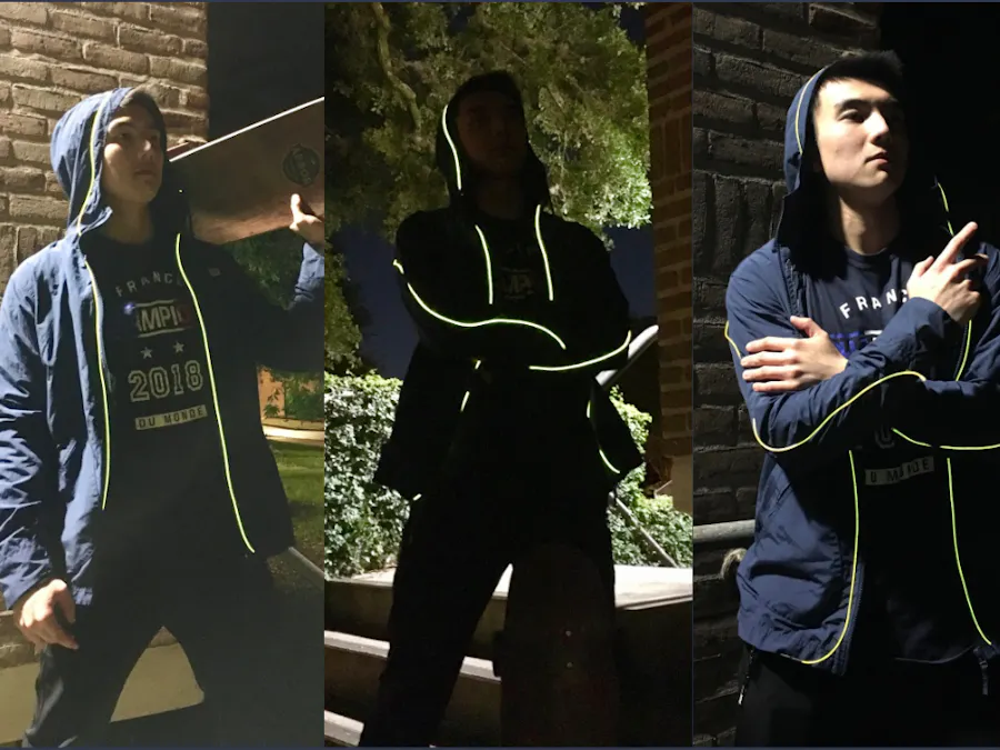
This is the Biometric Jacket, which we also call the STUPID jacket - Sensory Technology Utilizing Personal Indicator Jacket.
It gives you the ability to track your biometric data on the go. It collects your heart rate, your temperature, your steps, aggregates them, and then displays the results on a screen on your wrist, as you can see right now. Every sensor is embedded or sown onto the jacket, including the EL wires on the shoulders and on the back. The lights have 3 states - off by default, on, and the live heart rate mode, in which they would pulse at the rate of your heart rate.
Now, everyone is different, which is why our jacket needs to be calibrated for each individual. When it gets shipped to your home, the first thing you would do is run the calibration code - just walk for a couple of minutes, basically. Long story short, under the hood we need to tweak some thresholds for the accelerometer and the heart rate, the adjusted values get saved to EEPROM, then you upload the usual code, and it is now tailored just for you.
A bit about technical details.
All the communication is completed through I2C; we have a total of three I2C devices: heart rate and temperature sensor, an accelerometer which with a bit of math becomes a pedometer, and the OLED screen which displays the data on your wrist. On the wrist we also have two buttons - one to reset your step count, one toggles the lights between the three states. The lights are controlled through a MOSFET, and we use an inverter which takes in 12V DC and outputs about 100V AC to the EL wires. We have an 8 AA batteries power bank to run all this madness, and an Arduino as the brains.
We paid great attention to ensure that the user does not interact with the low-level stuff, with coding and circuitry - all you see is the user interface! All electronics are nicely packaged and stored on your back; every single cable, every EL wire, and sensor are sown or attached to the jacket. The jacket and calibration code for it run smoothly, you as a user do not need to bother yourself with it.
This is a functional prototype of our jacket, so while something would probably short-circuit under heavy rain for now, overall this is a solid functional representation of what the final product could be like.
About the Codes and the FrameworkThe framework collects the data from each individual live, aggregates it, and displays all that on the screen. Each sensor has a “routine” - a couple of functions that record the data from the sensors. We have a total of 7 routines: buttons, steps, temperature, heart rate, OLED screen, EL wires, and the One Routine to Bring Them All (and in the darkness bind them). Some of the routines are highly time-dependent: for instance, the heart sensor’s routine needs to be run multiple times a second so that we don’t accidentally miss the heartbeat. Some of the routines take quite a bit of time to run: the OLED display takes its sweet time to draw objects, and the accelerometer is in the middle between the two: it must be run frequently to not miss a step, and at the same time it takes ~150ms to run it because we need to calculate the vector of acceleration over time. Finding the balance between each routine and ensuring that we don’t lose any data was one of the tricky problems we tackled.
The accelerometer requires calibration for its accelerations thresholds - that is, how high does the acceleration need to be for us to consider it a step. Therefore what you would do is take a walk, count your steps, see if it matched the predictions, and adjust the threshold value accordingly using the buttons on your wrist. The threshold then gets saved to the EEPROM for the mainframe to fetch later. This calibration is enough to acquire basic functions, but it gets dicey once you begin to run or swing your arms too much. I guess those engineers at Apple/Google did a pretty darn good job counting my steps, and it’s gonna take us a bit more than a few hours to replicate that.
Future Improvements:
- Better pedometer algorithm. We are only using the accelerometer, but if we were to leverage the power IMU as a whole - throw in the gyro and the magnetometer into the mix - I am sure we would be able to figure out something solid.
- Consistency of the heart-rate sensor. All too many times it would think that the user is, in fact, dead - 0 beats. I wonder if there is some threshold deep in the library that we could tweak with. The results are also very noisy - therefore better averaging algorithm would be nice.
The heart and brain of the biometric jacket, a power bank as well as Arduino to which every single electronic component is connected to and functions off of, is a solid wiring complex residing in the back pocket of the jacket.
In this double layered jacket, all wiring starts at the back pocket, which radially extends between the two layers of the jacket, into each part of the body (see “Wiring and Electronics” section for more details). As for this center wiring complex, which includes a 8-AA-battery power bank, and Arduino Uno, an AC inverter, as well as other electronic pieces necessary to integrate all electronic wirings, it is glued and taped all-around in a most compact manner. Don’t let it fool you! Although at its first appearance it might or might not have been mistaken with an explosive device.
The integration of the jacket relied quite a bit on the attachment of the electronics to the jacket. Our group decided the most effective and professional looking method of attachment would be by sewing the components on. The EL Wire needed to be sown because otherwise it would be difficult to shape it however we pleased. A preliminary design was decided on and drawn onto the jacket with a light colored pencil. Then, the EL wire was taped along the line, and the sewing began. For the most part, the sewing is simple. We used a double strand of thread to make things a bit more secure and used a simple method of crossing over the EL wire and moving forward as such. As more was sown on, the tape would be removed, and this would continue for each of the 4 strands of EL wire attached to the jacket. 2 of them would be attached to either arm and around each shoulder, while the other 2 would be soldered together and sown to go around each side of the zipper and on the hood of the jacket. The wiring used to power the EL wire will enter a hole that would lead to the back of the jacket and allow it access to the Arduino. Besides the EL wire, the Accelerometer used to detect steps, would also need to be sown to a forearm. A hole would be made in the back of the jacket by the forearm it will attach to and then strewn through so that the sensor can be placed between the 2 layers of fabric. Once directed to where it needs to be, the sensor is securely attached by sewing through the attachment holes on the board. With that, all of the sewing is complete.
Future Improvements:
- For longer duration of the jacket’s performance, and higher stability in the structure of the power-processing complex in the long term, the next power bank will be made rechargeable.
- As the component on the biometric jacket with the highest significance, it is especially a priority to maintain a sound performance for this power-processing complex. Therefore, we consider enhancing implementing a 3D-printed exo-structure as well as a waterproof layer for structural integrity, and further security from the humid weather, to maximize the endurance of this complex as a part of the rain jacket.
About The Wristband
The wristband is an important component of the jacket. The OLED display as well as the heart rate sensor are loaded on an elastic wristband, for a close-to-skin measurement and convenient display of body temperature, heart-rate and step numbers.
As another user-friendly feature, two tiny (5x5mm) push-down buttons are mounted to the wristband, on the panel that fixates OLED display. The left button controls the state of the EL wires: with each push, the state immediately switch between “on”, “blinking with heart rate”, and “off”.
Future Improvements:
- Elevation of the heartrate sensor that is on the inner side of the wristband. In this way, the infrared sensor will be able to read more constant heartrate, without the tightened wristband adding too much overall restraint on the whole wrist.
- Further integration between the wristband and the jacket. At the moment, the wristband is firmly attached to the jacket, while the user still needs to put on the wristband independently after reaching their hands into the sleeve. With better special structure of the components, sewing, as well as the assistance of 3D modeling for further fixation, we will be able to integrate the wristband into the jacket, all the while preserving all its capacity as well as user interface.
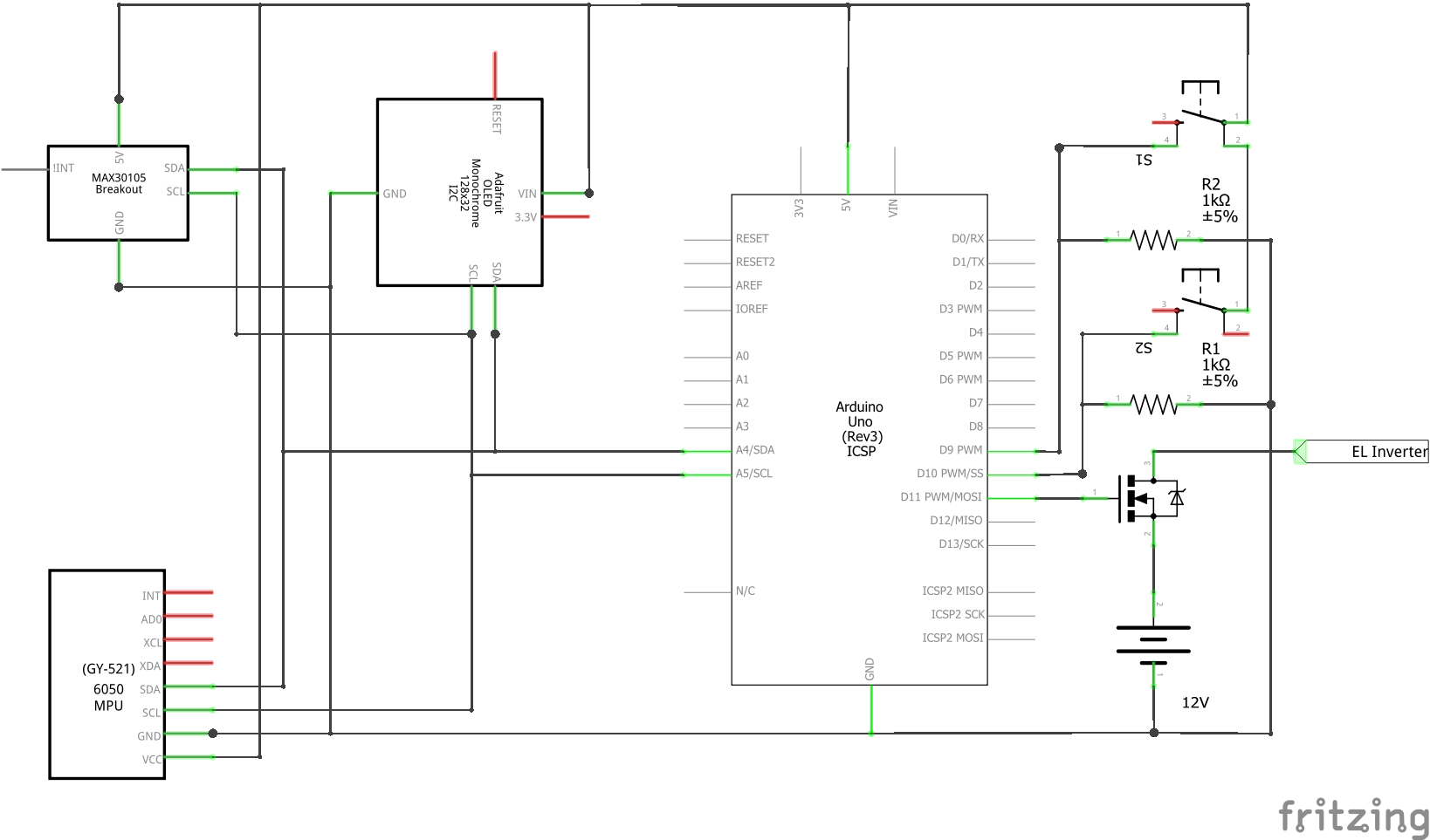
We are using I2C to communicate with the OLED display, heart rate sensor, and the IMU. Two buttons used to reset the step count and to toggle the lights connect two 2 digital pins set up as inputs, and the EL wires have a MOSFET controlling the lights; the MOSFET’s gate goes to a digital pin setup and an output. An 8AA battery power bank supplies 12 V to the inverter to power the EL wires, as well as the Arduino.
Every sensor has 4 male pins soldered to it (5V, GND, SDA, SCL), and we are running your regular jumper wires through the jacket to the Arduino, neatly placed on the back of the jacket. At this point, we are also hot gluing those jumper wires to ensure that the wires stay connected. The wiring diagram is presented below.
Future Improvements:
- Proper good wire connections; hot glue and jumper wires are great for a functional prototype, not so much for something you could actually wear on a daily basis.
- A rechargeable power bank - probably LiPo batteries. AA batteries are heavy and take up a lot of space; indeed, we were using them purely due to their accessibility - again, it’s a functional prototype. If making a proper product jacket, you would want to use some fat rechargeable LiPos.
Lastly, About How Inefficient LaunchPads Can Be
Originally, a LaunchPad was intended to be our primary processing unit, but we soon discovered how sparse the support for it was compared to more familiar programming boards. To use our sensors, it would require us to port already functional libraries to work with the LaunchPad, or make our own libraries from scratch. Both were deemed rather inefficient for our purposes, so we migrated to an Arduino Uno as our main board. The Arduino community is humongous and has out-of-the-box support for many components, including our chosen sensors. As such, we continued with the Arduino.


Comments