

Hardware components | ||||||
| × | 1 | ||||
| × | 1 | ||||
| × | 1 | ||||
| × | 1 | ||||
 |
| × | 1 | |||
| × | 1 | ||||
Software apps and online services | ||||||
 |
| |||||
| ||||||
There are a variety of cycle computers that are quite specialized and pack many features. I always ride with my mobile phone mounted on the head stem. It has a larger screen and web page interfaces can be customized to be high contrast and optimized UX.
This project is aimed at providing sensor data (think cadence and heartbeat) from a WiFi SOC (ESP8266) to a dashboard on the mobile phone. In order for it to actually replace a cycle computer, some trip readings would also need to be surfaced to the dashboard.
For the time being there is a demo of current MobileWeb at https://iot123.com.au/byko. The repository is at https://github.com/IOT-123/BYKO
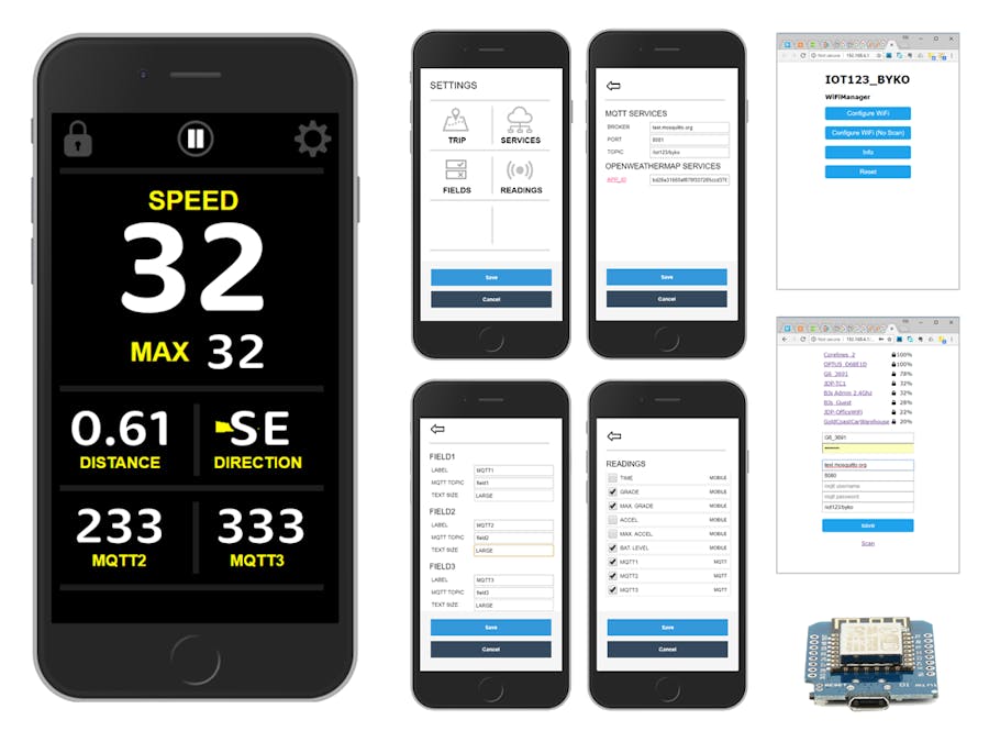
The LOCK button locks the orientation, goes fullscreen and keeps the screen awake (on Android). The PLAY/PAUSE controls the trip observation display. The SETTINGS button shows the following screens.
At this stage the SPEED and MAX. SPEED fields are static, and can't be replaced with other observations. The other 4 fields can be cycled from a short list of all available fields by tapping them. The short list is selected from the SETTINGS > READINGS screen.
THE READINGSAt this stage the list of Readings are:
GEOLOCATION API
- SPEED
- MAX. SPEED
- DISTANCE
- DIRECTION
- LATITUDE
- LONGITUDE
- POSITION ACCURACY
- ALTITUDE
- ALTITUDE ACCURACY
- POSITION FETCHED (timestamp)
OPENWEATHERMAP API (app_id required)
- WIND DIRECTION
- WIND SPEED
- WEATHER
- TEMP (C)
- PRESSURE (hPa)
- HUMIDITY (%)
- MIN. TEMP (C)
- MAX. TEMP (C)
- COUNTRY
- SUNRISE
- SUNSET
- WEATHER LOCATION
- WEATHER FETCHED (timestamp)
DEVICE or DERIVED
- DURATION
- TIME
- GRADE
- MAX. GRADE
- ACCEL.
- MAX. ACCEL.
- BAT. LEVEL
MQTT
- FIELD1
- FIELD2
- FIELD3
The short list makes it possible to only cycle fields that are important to you (or your phone supports).
THE MQTT FIELDSThe MQTT fields are customizable. The labels in the UI, the MQTT topic and the size of the value text can all be altered. At this stage there is only provision for 3; it is expected it will be zero to many when a templating engine is integrated.
THE SERVICESThe MQTT broker, port and root topic can be configured to match that of the ESP8266. A big omission here are the credentials for a private account. This will be addressed with the other UI framework improvements.
In order to use the OpenWeatherMap observations an app_id will need to be entered. The link takes you to where you can create a free account (or login and fetch your app_id).
THE TRIP SETTINGSIn the dashboard screen, it would be too haphazard to add these functions so they have their own screen. They are actions, so do not need to be saved. The buttons reset (set to zero) the DISTANCE and the MAX. SPEED. The MOCK COORDS. is for desktop development: it simulates LATITUDE, LONGITUDE, SPEED, and DIRECTION when you hit the play button.
ESP8266 CONFIGURATIONAfter installing the firmware for the Wifi SOC, the connection for the Hotspot and MQTT broker are configured with the tzapu/WifiManager.
Start the Hotspot on the phone you will use on the ride. Power up the ESP8266.
On a PC prior to your first use: after a minute browse the available networks and choose and connect to IOT123_BYKO (the access point spun up by the ESP8266). The password will be whatever you defined in the sketch. When it connects, a Captive Portal should appear in your browser (like that pictured).
- Choose Configure Wifi.
- Select the Mobile Phone Hotspot.
- Enter the MQTT details and save.
- Wait a minute and reboot.
Now every time the ESP8266 boots it will try to connect to that network, then publish to that MQTT broker.
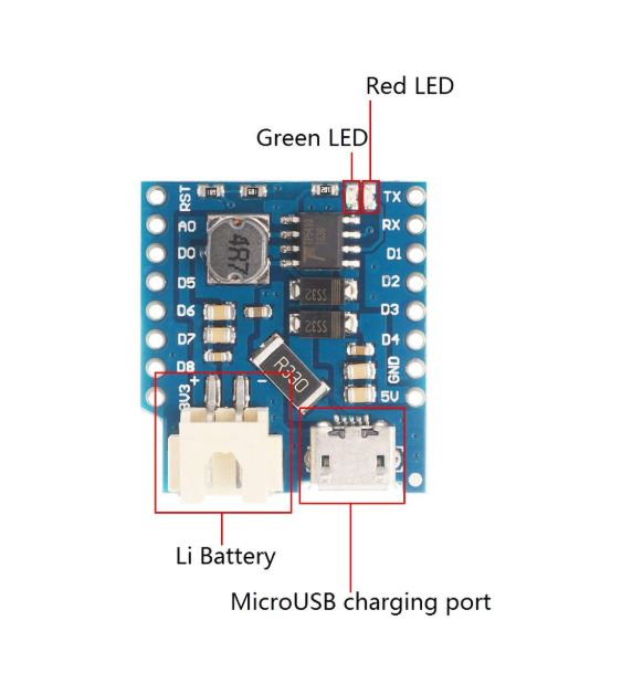
I have added a Helmet mounted 18650 for the D1M WIFI BLOCK here.
In future installments, I will be developing a circuit with the following:
- 18650 battery & housing
- Small inter-linked solar cells (~25mm x 30mm)
- Universal PCB (may or may not lead to a custom PCB)
- TP4056 with protection (DW01A)
- Diodes, Resistors
- RGB LED (possible self flashing)
- Momentary Button
- Vibrate actor
- SPDT Power Switch
WHY TP4056 instead of Battery Shield?
I intend to mount Small Solar Panels on the surface of the helmet. Also the Shield uses A0 (which may be disabled). Yersinia gives a very good review of the Battery Shield here. The main take-away is:
Studying the circuit it seems that the 5 Volt coming from the USB, is connected to the 5 Volt pin of the shield, only through an SS32 Skottky diode. In itself that is no problem, unless one decides to use another input to that connector, e.g. a solar cell. The Wemos D1 mini has an RT9013 LDO regulator that has a max input of 5.5 Volt with an absolute Max rating of 6 Volt. Considering that the SS32 Skottky diode has a forward voltage of 200 mV @ 200mA, a voltage of > 6.2 on the USB connector of the battery shield (say a 6 Volt solar panel on a bright day) could already kill the RT9013 LDO on the Wemos D1 board, Even though Wemos states the shield can be supplied with 10 Volt, but maybe that is without it being connected to the Wemos D1 mini.
The caveat to this is if you need a 5V rail in your circuit, the battery shield offers a fairly efficient (between 85-90%) boost converter (TP5410), and the TP4056 is left wanting.
POSSIBLE HARDWARE BEHAVIORSMomentary Button
- 3 seconds held during boot
- Format SPIFFS
- Reset WifiManager
- Reboot
RGB Indicator
- Flash amber in Access Point Mode
- Flash Red till connected to Wifi Hotspot
- Stay Green (or intermittent) when connect to Hotspot.
- Flash differently for SPIFFS Format
Vibration Actor
- Pulse till connected to Hotspot.
As well as the basic hardware developments above, consider:
- A proximity sensor (< 1m) that triggers a photo capture of the offenders rear (plate) using a 90 degrees periscope attachment (that's a lot of photos).
- Timed or evoked (possibly voice command) photo capture during trip.
- The Pulse Sensor connected to the Ear.
- The RF Receiver picking up Cadence
- All (or a defined subset) of the on-phone readings, can be published to MQTT or posted to a rest service.
- User defined actions (possibly triggered by voice command) published to MQTT, that the ESP8266 subscribes to and acts on.


Comments