/*this program is intened to take a temperature reading and publish it to the cloud. It will also
be notified when another temperature sensor takes a reading and illuminate a status LED as a result.
Additionally it will be notified of an event when an attic fan is switched on and illuminate a status
LED for the duration that it is powered on.*/
// This #include statement was automatically added by the Particle IDE.
#include <OneWire.h>
/************************************************************************
This sketch reads the temperature from a 1-Wire device and then publishes
to the Particle cloud. From there, IFTTT can be used to log the date,
time, and temperature to a Google Spreadsheet. Read more in our tutorial
here: https://docs.particle.io/tutorials/topics/maker-kit
This sketch is the same as the example from the OneWire library, but
with the addition of three lines at the end to publish the data to the
cloud.
Use this sketch to read the temperature from 1-Wire devices
you have attached to your Particle device (core, p0, p1, photon, electron)
Temperature is read from: DS18S20, DS18B20, DS1822, DS2438
Expanding on the enumeration process in the address scanner, this example
reads the temperature and outputs it from known device types as it scans.
I/O setup:
These made it easy to just 'plug in' my 18B20 (note that a bare TO-92
sensor may read higher than it should if it's right next to the Photon)
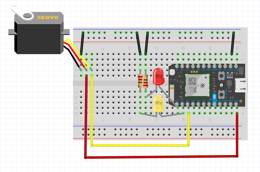
D3 - 1-wire ground, or just use regular pin and comment out below.
D4 - 1-wire signal, 2K-10K resistor to D5 (3v3)
D5 - 1-wire power, ditto ground comment.
A pull-up resistor is required on the signal line. The spec calls for a 4.7K.
I have used 1K-10K depending on the bus configuration and what I had out on the
bench. If you are powering the device, they all work. If you are using parisidic
power it gets more picky about the value.
************************************************************************/
OneWire ds = OneWire(D4); // 1-wire signal on pin D4
unsigned long lastUpdate = 0;
float lastTemp;
int status0 = D0;
int status1 = D1;
void setup() {
Serial.begin(9600);
// Set up 'power' pins, comment out if not used!
pinMode(status0, OUTPUT);
pinMode(status1, OUTPUT);
//digitalWrite(D3, LOW);
//digitalWrite(D5, HIGH);
Particle.subscribe("status_eanderson", StatusLight); //subscribe to the fan event
Particle.subscribe("temperature_carter", templed); //subscribe to the event published by the other sensor
//flash each LED to show the program has setup
digitalWrite(status0, HIGH);
delay(500);
digitalWrite(status0, LOW);
delay(500);
digitalWrite(status1, HIGH);
delay(500);
digitalWrite(status1, LOW);
delay(500);
}
// the following portion of the code was taken from the maker kit example "tutorial #4: temperature logger"
// up to here, it is the same as the address acanner
// we need a few more variables for this example
void loop(void) {
byte i;
byte present = 0;
byte type_s;
byte data[12];
byte addr[8];
float celsius, fahrenheit;
if ( !ds.search(addr)) {
Serial.println("No more addresses.");
Serial.println();
ds.reset_search();
delay(250);
return;
}
// The order is changed a bit in this example
// first the returned address is printed
Serial.print("ROM =");
for( i = 0; i < 8; i++) {
Serial.write(' ');
Serial.print(addr[i], HEX);
}
// second the CRC is checked, on fail,
// print error and just return to try again
if (OneWire::crc8(addr, 7) != addr[7]) {
Serial.println("CRC is not valid!");
return;
}
Serial.println();
// we have a good address at this point
// what kind of chip do we have?
// we will set a type_s value for known types or just return
// the first ROM byte indicates which chip
switch (addr[0]) {
case 0x10:
Serial.println(" Chip = DS1820/DS18S20");
type_s = 1;
break;
case 0x28:
Serial.println(" Chip = DS18B20");
type_s = 0;
break;
case 0x22:
Serial.println(" Chip = DS1822");
type_s = 0;
break;
case 0x26:
Serial.println(" Chip = DS2438");
type_s = 2;
break;
default:
Serial.println("Unknown device type.");
return;
}
// this device has temp so let's read it
ds.reset(); // first clear the 1-wire bus
ds.select(addr); // now select the device we just found
// ds.write(0x44, 1); // tell it to start a conversion, with parasite power on at the end
ds.write(0x44, 0); // or start conversion in powered mode (bus finishes low)
// just wait a second while the conversion takes place
// different chips have different conversion times, check the specs, 1 sec is worse case + 250ms
// you could also communicate with other devices if you like but you would need
// to already know their address to select them.
delay(1000); // maybe 750ms is enough, maybe not, wait 1 sec for conversion
// we might do a ds.depower() (parasite) here, but the reset will take care of it.
// first make sure current values are in the scratch pad
present = ds.reset();
ds.select(addr);
ds.write(0xB8,0); // Recall Memory 0
ds.write(0x00,0); // Recall Memory 0
// now read the scratch pad
present = ds.reset();
ds.select(addr);
ds.write(0xBE,0); // Read Scratchpad
if (type_s == 2) {
ds.write(0x00,0); // The DS2438 needs a page# to read
}
// transfer and print the values
Serial.print(" Data = ");
Serial.print(present, HEX);
Serial.print(" ");
for ( i = 0; i < 9; i++) { // we need 9 bytes
data[i] = ds.read();
Serial.print(data[i], HEX);
Serial.print(" ");
}
Serial.print(" CRC=");
Serial.print(OneWire::crc8(data, 8), HEX);
Serial.println();
// Convert the data to actual temperature
// because the result is a 16 bit signed integer, it should
// be stored to an "int16_t" type, which is always 16 bits
// even when compiled on a 32 bit processor.
int16_t raw = (data[1] << 8) | data[0];
if (type_s == 2) raw = (data[2] << 8) | data[1];
byte cfg = (data[4] & 0x60);
switch (type_s) {
case 1:
raw = raw << 3; // 9 bit resolution default
if (data[7] == 0x10) {
// "count remain" gives full 12 bit resolution
raw = (raw & 0xFFF0) + 12 - data[6];
}
celsius = (int)raw * 0.0625;
break;
case 0:
// at lower res, the low bits are undefined, so let's zero them
if (cfg == 0x00) raw = raw & ~7; // 9 bit resolution, 93.75 ms
if (cfg == 0x20) raw = raw & ~3; // 10 bit res, 187.5 ms
if (cfg == 0x40) raw = raw & ~1; // 11 bit res, 375 ms
// default is 12 bit resolution, 750 ms conversion time
celsius = (int)raw * 0.0625;
break;
case 2:
data[1] = (data[1] >> 3) & 0x1f;
if (data[2] > 127) {
celsius = (int)data[2] - ((int)data[1] * .03125);
}else{
celsius = (int)data[2] + ((int)data[1] * .03125);
}
}
// remove random errors
if((((celsius <= 0 && celsius > -1) && lastTemp > 5)) || celsius > 125) {
celsius = lastTemp;
}
fahrenheit = celsius * 1.8 + 32.0;
lastTemp = celsius;
Serial.print(" Temperature = ");
Serial.print(celsius);
Serial.print(" Celsius, ");
Serial.print(fahrenheit);
Serial.println(" Fahrenheit");
//if(fahrenheit > 75){
{
// now that we have the readings, we can publish them to the cloud
String temperature = String(fahrenheit); // store temp in "temperature" string
Particle.publish("temperature_swanger", temperature); // publish to cloud with event name "temperature_swanger"
delay(10000); // 10 second delay between readings
}
}
void StatusLight(const char *event, const char *data) {
if (strcmp(data,"ON")==0){ //if the fan has been switched on, trigger the green status LED
digitalWrite(status0,HIGH);
}
else if (strcmp(data,"OFF")==0){ //if the fan has been switched off, turn the green status LED off
digitalWrite(status0,LOW);
}
}
void templed(const char *event, const char *data) { //if the other temperature sensor has taken a reading, trigger the white LED
if (data){ //if the other temperature sensor has taken a reading, trigger the white LED
digitalWrite(status1,HIGH);
delay(5000); //illuminate for 5 seconds before turning off
digitalWrite(status1,LOW);
}
}


_3u05Tpwasz.png?auto=compress%2Cformat&w=40&h=40&fit=fillmax&bg=fff&dpr=2)
Comments