


Hardware components | ||||||
 |
| × | 2 | |||
| × | 1 | ||||
 |
| × | 2 | |||
 |
| × | 1 | |||
 |
| × | 2 | |||
 |
| × | 2 | |||
| × | 1 | ||||
| × | 2 | ||||
 |
| × | 3 | |||
 |
| × | 1 | |||
 |
| × | 1 | |||
 |
| × | 1 | |||
| × | 1 | ||||
Software apps and online services | ||||||
 |
| |||||
Hand tools and fabrication machines | ||||||
| ||||||
| ||||||
| ||||||
| ||||||
| ||||||
Whether you want to brag how fast you can go, or if you just want to track your weekend bicycle excursion, this project allows you to keep tabs on your distance, speed and acceleration. Two Particle Photons and a Hall-Effect sensor are used to measure the revolutions of the back tire of the bicycle. This allows for the calculation of distance, speed, and acceleration.
Electrical Setup
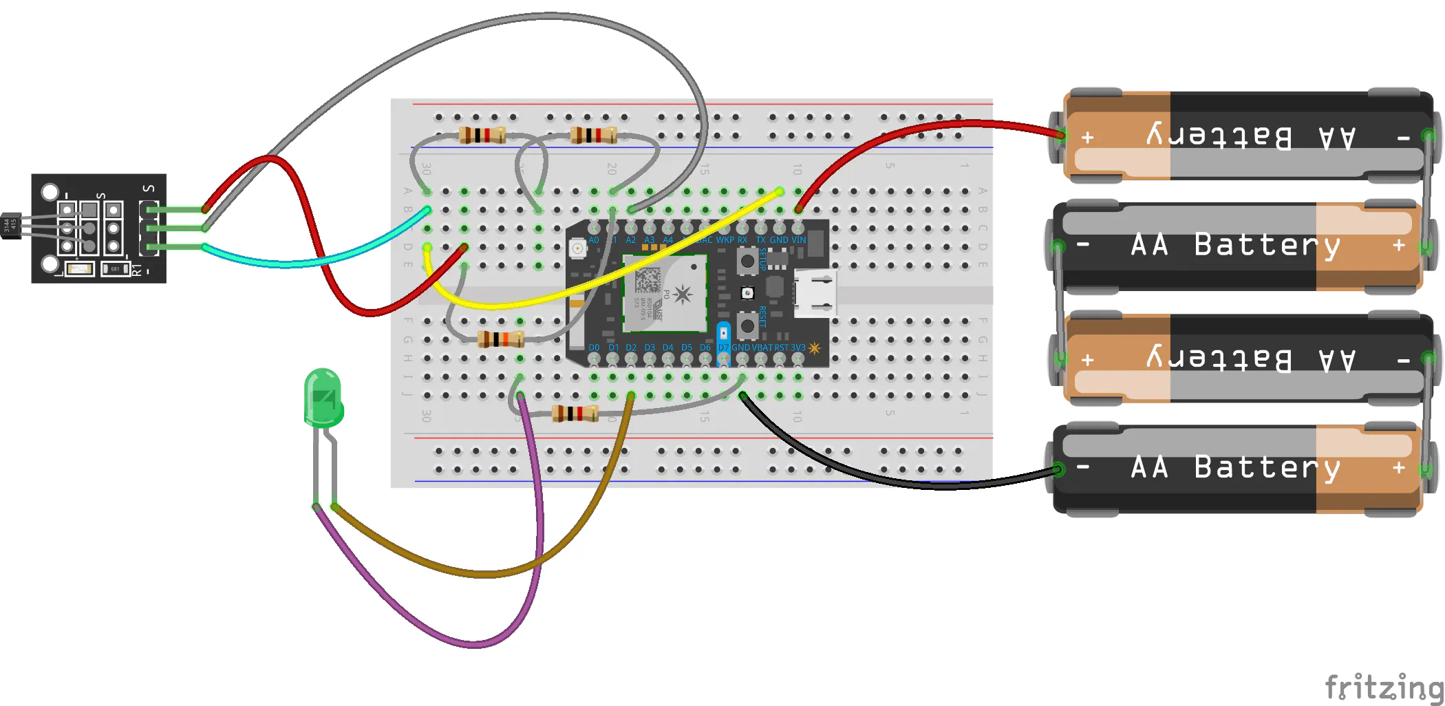
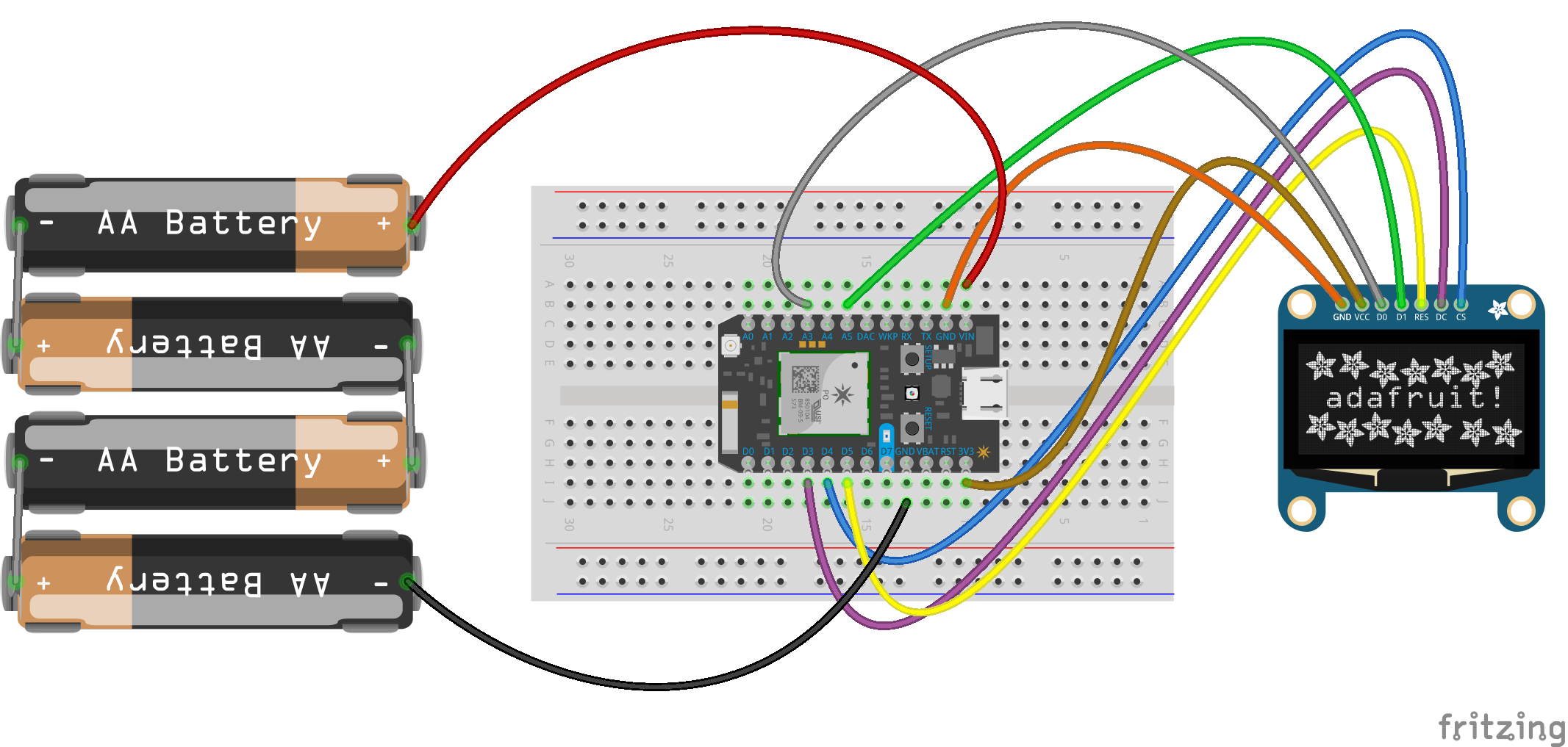
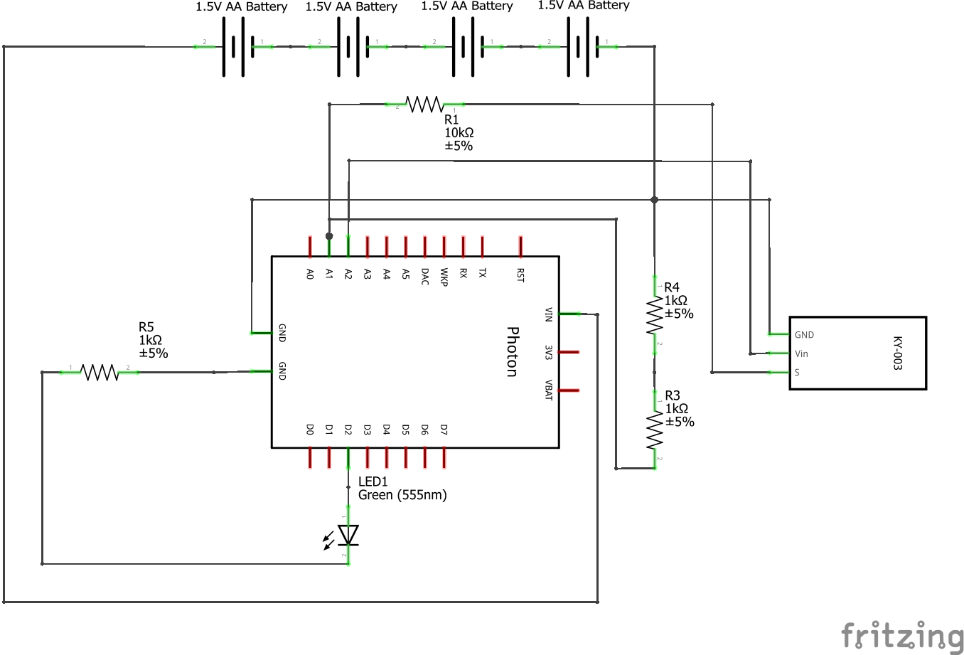
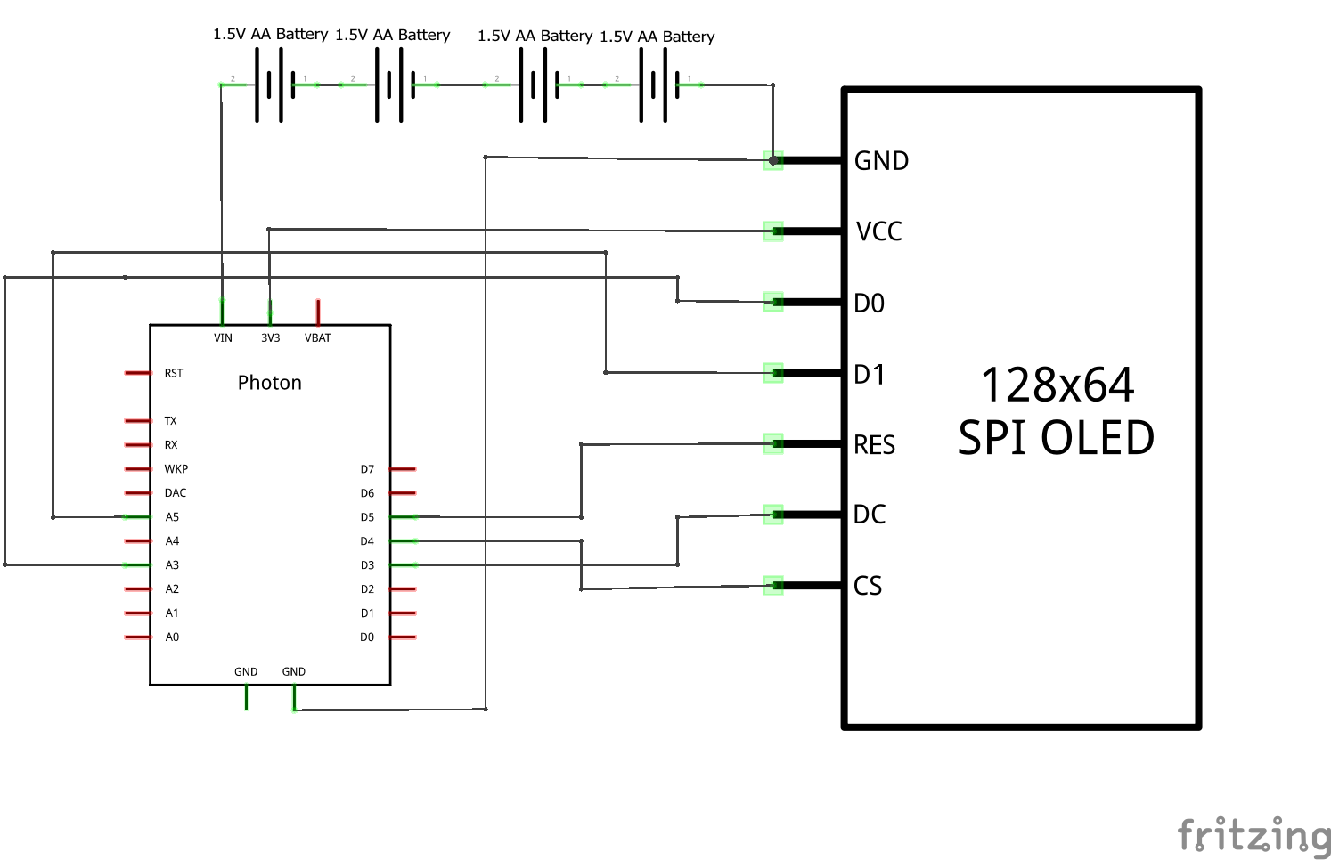
For the electrical component setup, we need two particle photons and two small solder-less breadboards. The particle photons can be purchased for $19.00 each from Particle. We also need some jumper wires, two 4-AA battery holders, various resistors, a hall effect sensor, and an OLED Display screen. Refer to the schematics section for a circuit diagram.
MountingSetup
For the mounting setup, we used a 3d printer to make the enclosures. The.stl files can be found in the attachments section.
Depending on your bicycle and how you want to mount the enclosures, you may need to edit some of the dimensions. This particular setup used a diameter of 0.5” for the bicycle stem segment.
Zip ties were used to fasten the mounts onto the bicycle, but more permanent options such as metal ties could also be used.
Putting the Electrical and Mounting Setups Together
Speedometer Photon [Display Module]
Perhaps the most difficult part of this project is fitting the electrical component setup into the enclosures. It is advised to take the side tabs off of the breadboard used in the speedometer for extra space. The breadboard should slide into place and "lock" due to the upward deflection of the plastic.
We also need to run cables out to the display. We used female to female wires attached to male to male wires, since not many female-male wires can actually fit in the enclosure due to height limitations. The female to female wires were bundled like so:
The Male-Male Wires were then attached and secure:
If the connections between the two are not very secure, you may want to tape the two bundles together at this intersection. The ones we used snapped into place well, and required minimal taping. Once the cable assembly is put together, feed it through the slot on the front of the speedometer:
You may want to use a small string to guide it. Also pictured is the battery pack inserted into the bottom compartment. It simply slides into place and is held in place by the door. Now comes the most difficult part, fitting the circuit into the upper compartment. We advise using tape to secure wires down so they don't slip out of the breadboard. Alternatively, you could just solder the wires, but that would be much more time intensive. The very organized circuit insertion:
Again, notice that the breadboard has been reduced in size to accommodate for the wires. One last thing to do is to attach the screen. A small spacer block was printed for adjustable screen height. You can go without this block, but if you want to adjust what angle the screen is at to you on the bicycle, this is one way to do it. The spacer we printed looked like:
After either securing the screen using the spacer, or just using the configuration in the original model, the speedometer photon is almost complete. All that is needed is to insert the battery pack into the holder, and switch it on!
Data Acquisition Photon [Hall Effect Sensor Module]
This assembly is much easier than the Speedometer Photon. Once the circuit is assembled, the breadboard can just be slid into place. The only precautions needed is to first attach the LED to the breadboard, feed it through one of the enclosure holes, and secure it to the enclosure with your preferred adhesive. This can be seen in the final build:
We have a little bit to go before we have completed this assembly however. Once the circuit is assembled, it is advised to secure the wires to the breadboard using tape. Alternatively, one could use solder for this.
Once the wires have been taped down, feed the hall-effect sensor and battery pack wires out of the 2 remaining holes in the enclosure.
The wires should look like the above image. Now, all that's left to do is slide the breadboard in, slide the battery pack in, and slide the door closed. Also, remember to flash the code to the photon. With both Photon circuits assembled and placed in their enclosures, we can then begin mounting them onto the bicycle.
Mounting
SpeedometerPhoton
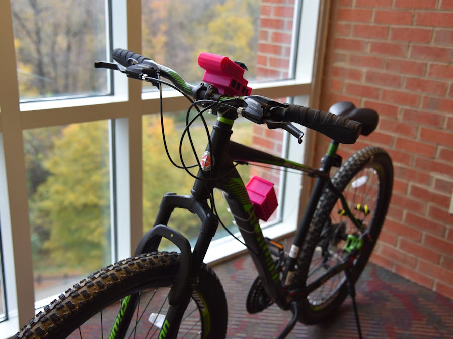
The only step is to zip tie the enclosure to the bike as pictured:
Data Acquisition Photon
This Photon is easy to mount, but requires some additional work in regards to the hall effect sensor. First, mount the enclosure onto the bike as pictured:
Once the enclosure is mounted, take the wires and tape them to the frame, bundling them as you go. For superior looks and organization, one could braid the wires as so:
Run your wires towards the back of the bike. You should end with a hall effect sensor placement looking something like this:
Also seen in the photo is the magnet placement. For this project, we attempted to first use traditional bicycle spoke magnets, but found that they were not strong enough to trigger the hall effect sensor. The fix that we came up with was to use stronger, albeit uglier, magnets. The important detail in mounting the magnets is make sure that they are all equal distance from the center of the wheel, and are equally spaced along the turn of the wheel. We chose to use 4 magnets, but the code is designed so that a single variable controlling the number of magnets can be changed to customize the number of magnets used on the bicycle. The accuracy of the speedometer goes up the more magnets are present. However, keep in mind that the Photon can collect data no faster than it's clock speed (120MHz). The finished setup looked something like this:
At this point the entire assembly is finished. The finished product should look something like this:
In order to estimate the velocity of the bike, a discrete form of the derivative of position with respect to time is required. Velocity is estimated by the change in position divided by the change in time. To find the distance, the number of rotations of the wheel and the distance traveled per rotation of the wheel is used. The Hall Effect Sensor module and magnets mounted on the bike around the wheel are used to determine the number of rotations (number of passes of the magnet by the Hall Effect Sensor divided by the number of magnets) and a tape measure is used to determine the distance traveled for a rotation of the wheel. For every submission of data from the Hall Effect Sensor module to the Display module there is a 3.3 second window of time for which the passes are observed. When the first pass within the 3.3 second window is detected (pass zero), a timer starts and adds up time between passes. The parameters used from the 3.3 second window to determine the average velocity are the number of passes after pass zero and the time between pass zero and the final pass. The velocity is calculated using the parameters listed above through the code here:
calculatedvelocity = ((simplefloat-(1))*(calibration/(magcount*timepass*5280*12/(3600*1000))));
// simplefloat - Number of Passes in 3.3 second window including pass zero
// calibration - Distance traveled per rotation of the wheel in Inches
// magcount    - Number of Magnets on the Wheel
// timepass    - time passed between pass zero and the final pass in milliseconds
// conversions - 12 inches in 1 foot
//               5280 feet in 1 mile
//               3600 seconds in 1 hour
//               1000 seconds in 1 millisecond
    1 Line, 8 Comment Lines
For data submitted to the Thingspeak live charts, raw number of passes and the time window of 16.5 seconds (Thingspeak requires 15 seconds between data submissions) are used to determine the average velocity. The error times are considered insignificant due to the large time window for data submitted to Thingspeak.
Velocity is graphed live using a webhook integration to send particle publish data from the photon to Thingspeak. Using MATLAB, the velocity data is used to chart distance traveled, velocity, acceleration, and idle time. Distance traveled and acceleration are determined via discrete calculations of kinematic equations and using the assumption that unknown constants are zero. Idle time is the time for which the Hall Effect Sensor is turned on but there is no significant movement (speed less than 1 MPH). All of these charts for the device used for this project can be access publicly here: Thingspeak Graphs, Note: Sometimes Thingspeak does not load the MATLAB code correctly and returns an error, refreshing the page is required to fix this. Here is an example of the graphs page with data from testing on 11/09/2018:
Hall Effect Sensor Module [Breadboard View]

Hall Effect Sensor Module [Circuit Diagram]


Comments