



Hardware components | ||||||
 |
| × | 1 | |||
| × | 1 | ||||
| × | 1 | ||||
| × | 1 | ||||
| × | 1 | ||||
| × | 1 | ||||
Software apps and online services | ||||||
| ||||||
What is it?VitalSight Industrial is a handheld, web-based tool used for predictive maintenance. It is built using the Arduino UNO Q and App Lab. The system uses a high-speed global shutter USB camera, local video processing, Eulerian Video Magnification (EVM), FFT frequency analysis, lens calibration tools, and an STM32 LED matrix for visual feedback. It helps technicians see tiny mechanical vibrations with their own eyes, completely wirelessly and without touching the machine.
Think of it as a portable visual stethoscope for industrial equipment like pumps, motors, fans, and pipes. Instead of spending time installing wired sensors for a quick check, a technician can just point the camera at the machine, calibrate the lens, record a video, magnify the motion, and check the frequency spectrum right from a web browser.
Why I Built ThisMost mechanical issues start with tiny changes in how a machine vibrates. Things like misalignment, loose parts, bearing wear, or structural fatigue usually start as micro-motions that we cannot see. While traditional vibration analysis works great, it requires physical sensors, cables, and direct access to the machine. I wanted to create a faster, safer, and completely contactless way to inspect equipment from a safe distance using video as a vibration sensor.
How it Works (Main Use Case)The setup is very straightforward for Smart Predictive Maintenance. A technician walks up to a running pump or motor and turns on the VitalSight Industrial unit. They connect to the local web interface using a phone or tablet, point the camera at the machine, and follow a simple workflow: calibrate the lens, check the image quality, record a short video, apply EVM to magnify the motion, analyze the FFT spectrum, and download the results.Web Interface
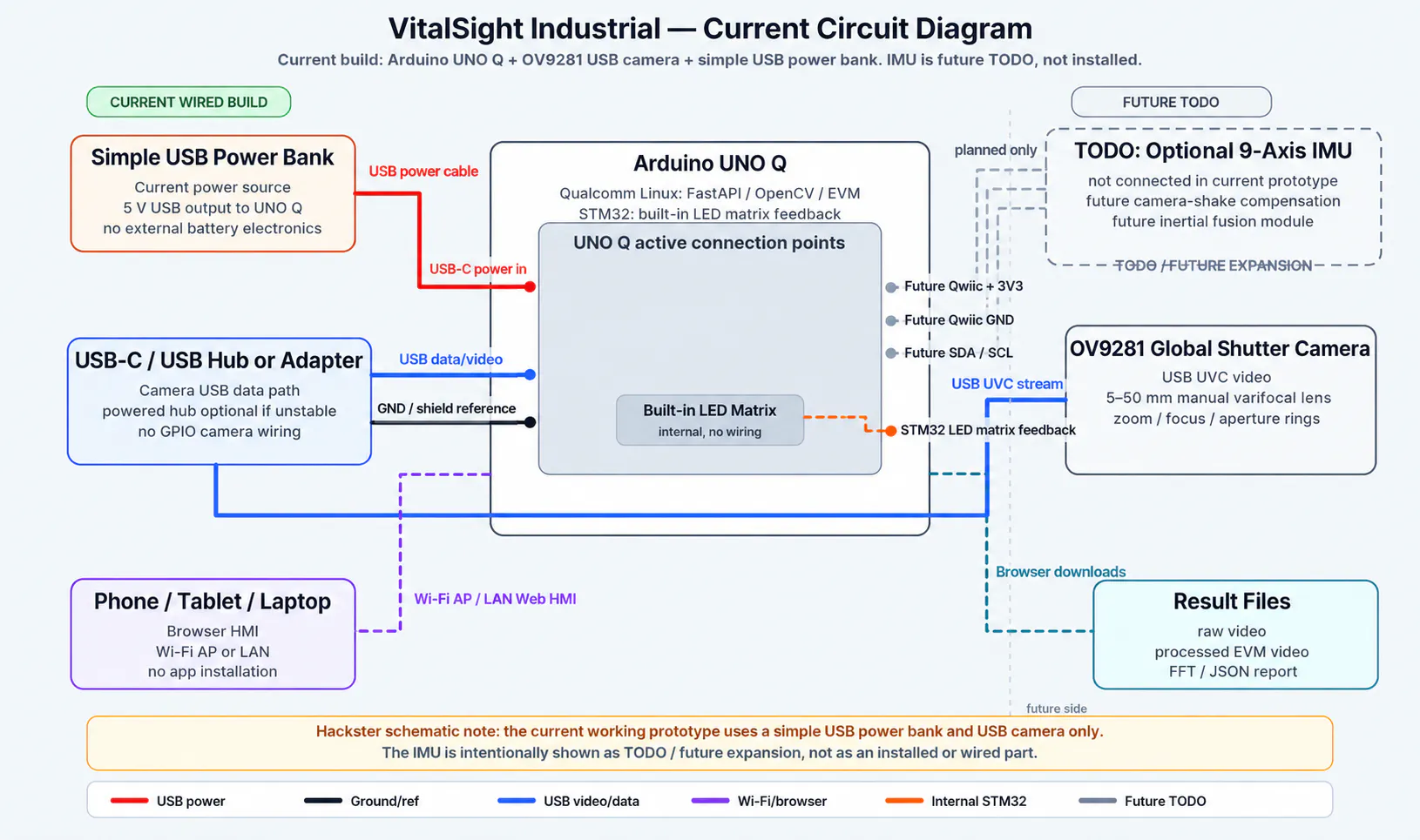
System Architecture & HardwareThe system uses the dual-processor setup of the Arduino UNO Q:
- The Qualcomm Linux side handles the heavy lifting: the FastAPI backend, the web interface, camera capture, live preview via WebSockets, OpenCV processing, EVM, FFT analysis, file downloads, and communication with the STM32.
- The STM32 side controls the built-in LED matrix to give real-time status updates (like ready, recording, analyzing, or errors).
For the hardware, the prototype uses the Arduino UNO Q, an OV9281 global shutter USB camera, a 5-50 mm manual varifocal lens, a USB-C hub, and a power supply. You can use it handheld or on a tripod. A global shutter camera is necessary here because regular rolling shutter cameras create fake motion artifacts when recording vibrations.Key Features
- Web Interface: Works on both desktop and mobile. On mobile, it automatically switches to a simpler layout so a technician in the field can easily focus on live preview, recording, and processing.
- Lens Calibration Assistant: Adjusting a manual three-ring lens (zoom, focus, aperture) can be tricky. This assistant guides you through 3 steps: it sets up the exposure while you open the aperture, turns on focus peaking with a live focus score while you adjust the focus, and then lets you reset normal settings and lock the rings.
Video Quality Assistant: This checks your setup before processing. It analyzes brightness, noise, and clipping to give you a quick report and recommendations so you get the cleanest data possible.
- Video Quality Assistant: This checks your setup before processing. It analyzes brightness, noise, and clipping to give you a quick report and recommendations so you get the cleanest data possible.
- Eulerian Video Magnification (EVM): This is the core feature. It takes the video, filters the motion, amplifies it, and rebuilds the video so you can see the amplified vibrations clearly. The main mode used for industrial checks is motion magnification using a Laplacian pyramid.
- FFT Frequency Analysis: This helps you find the exact vibration frequencies. It makes it easy to spot abnormal behavior, find resonance issues, and properly tune the EVM filters.
- Other Features: You can upload existing videos to test the EVM algorithm, monitor the hardware stats (CPU, RAM, temperature) to see if your settings are too heavy for the board, and download the raw videos, processed videos, or JSON reports for documentation.
Sustainability & ScalabilityBy catching mechanical issues early, VitalSight Industrial helps teams fix problems before a total breakdown happens. This reduces wasted spare parts, emergency repair costs, and production downtime.
The concept can easily expand to other areas like HVAC systems, robotics, structural monitoring, or even drone-based inspections. Since it is web-based, you don’t need to install any special software—it works on any device.
Future Plans (AI & IMU)Future Plans: AI, IMU and Motorized Lens Control
The current prototype focuses on the working contactless inspection workflow: video acquisition, lens calibration, image quality checking, EVM processing, FFT analysis, browser operation, downloads, and STM32 LED matrix feedback.
The IMU-assisted stabilization and AI fault classification features are planned as future expansion modules. They are not installed or fully implemented in the current prototype.
The next major development step is to add an IMU module for camera-shake compensation. This would help the system separate real machine vibration from handheld camera movement.
Another important future improvement is motorized control of the camera lens. The current OV9281 camera uses a manual 3-ring varifocal lens for zoom, focus and aperture. A future mechanical upgrade could use 3D printed rings and small servo motors to rotate these lens rings directly from the web interface. This would allow automatic focus scanning, remote zoom adjustment, aperture optimization, and repeatable camera presets.
The final goal is to make VitalSight Industrial easier to use as a handheld field tool, with less manual lens adjustment and more repeatable measurement conditions.Future TODO List
The current prototype already implements the core contactless workflow: camera acquisition, lens calibration, video quality check, recording, Eulerian Video Magnification, FFT analysis, browser-based operation, downloads, and STM32 LED matrix feedback.
Some advanced features are planned for the next development stages and are intentionally marked as future work.
- IMU-Assisted Stabilization
The original concept includes an IMU-assisted stabilization layer. This is not installed in the current hardware prototype yet. The planned IMU module will be used to measure camera movement and help distinguish real machine vibration from handheld camera shake. The goal is to synchronize IMU data with video frames and compensate for ego-motion before applying EVM.
Planned functions:
- 9-axis IMU integration;
- IMU status panel in the web interface;
- IMU data logging with video timestamps;
- camera-shake estimation;
- software-based stabilization;
- future AI-assisted inertial/video fusion.
In the current version, the system works best when the camera is mounted on a tripod or held as steadily as possible.
- Motorized Zoom, Focus and Aperture Control
The current camera uses a manual 3-ring varifocal lens: zoom ring, focus ring and aperture ring.
At this stage, these rings are adjusted manually by the user with help from the Lens Calibration Assistant and the live focus peaking overlay.
A future mechanical upgrade is planned using 3D printed rings or gear adapters mounted around the three lens rings. Small servo motors or geared micro-motors could rotate each ring under software control.
The goal is to control the lens directly from the web interface.Planned functions:
- 3D printed gear rings for zoom, focus and aperture;
- servo or micro gear-motor mounts;
- web-based zoom control;
- web-based focus control;
- web-based aperture control;
- automatic critical-focus routine;
- focus-score feedback loop;
- automatic aperture/depth-of-field optimization;
- saved lens presets for different working distances.
This would make the tool much easier to use in the field because the technician would not need to touch the lens during setup.
- Automatic Focus and Auto-Zoom Workflow
The Lens Calibration Assistant currently guides the user manually. A future version could make this process semi-automatic.
The camera would zoom in, scan the focus ring, measure the focus score, find the best focus position, and then zoom back out to the desired frame.
Planned workflow:
1. User selects the target object or ROI.
2. System zooms in.
3. Focus motor scans through the focus range.
4. Software measures the sharpness/focus score.
5. Best focus point is selected.
6. System zooms back out.
7. Aperture is adjusted for the required depth of field.
8. Settings are stored as a lens preset.
This would create more repeatable data for EVM and FFT processing.
- AI Fault Classification
The current system visualizes and analyzes vibration but does not yet provide certified automatic diagnosis.
A future AI layer could classify common mechanical fault patterns using vibration spectra, EVM motion features and historical measurements.
Planned classes:
- normal operation;
- imbalance;
- misalignment;
- looseness;
- resonance;
- bearing-related vibration;
- cavitation-like behavior.
The output would be shown as an experimental diagnostic suggestion, not as a certified maintenance decision.
- Real Displacement Calibration
A future version should include a known-size calibration target so the software can convert pixel motion into approximate physical displacement.
Planned functions:
- printed calibration marker;
- pixels-per-millimeter estimation;
- ROI-based displacement tracking;
- displacement trend over time;
- confidence score based on focus, lighting and target quality.
- Rugged Handheld Enclosure
The prototype can currently be used on a tripod or handheld setup. A future version should include a rugged 3D printed or machined enclosure.
Planned enclosure features:
- Arduino UNO Q mounting;
- camera mount;
- USB power bank compartment;
- cable strain relief;
- ventilation;
- tripod thread;
- hand grip;
- optional servo lens-control mechanism;
- service access for the camera and lens.
- Maintenance Report Generation
The current version allows downloading raw video, processed video and JSON results.
A future version could automatically generate a maintenance report.
Planned report contents:
- machine name;
- date and time;
- camera settings;
- EVM settings;
- FFT spectrum;
- dominant frequency;
- raw frame;
- magnified result;
- technician comments;
- recommended follow-up actions.
LimitationsIt is important to note that VitalSight Industrial is currently a prototype and not a certified industrial tool. The accuracy depends heavily on lighting, camera stability, distance, and focus. It should be used as a handy visual aid to support diagnostics, not as a total replacement for certified vibration measurement gear.ConclusionOverall, VitalSight Industrial shows how you can use the Arduino UNO Q and App Lab to build a practical, edge-computing tool for predictive maintenance.
By combining high-speed video, a simple web interface, local computer vision, EVM, and FFT analysis, the project successfully turns tiny, invisible vibrations into clear visual data that you can easily see, analyze, and download.


Comments